GE Digital Energy Power Quality Operating Manual Digital Energy™ SNMP / WEB ADAPTER P/N 1018959 3-ph SNMP/Web plug-in adapter P/N 1019070 1-ph SNMP/Web plug-in adapter P/N 23954 SP SNMP/Web plug-in adapter P/N 1019071 1-ph SNMP/Web external adapter GE Consumer & Industrial SA General Electric Company CH – 6595 Riazzino (Locarno) Switzerland T +41 (0)91 / 850 51 51 F +41 (0)91 / 850 51 44 www.gedigitalenergy.
Model: 3-ph SNMP/Web plug-in adapter 1-ph SNMP/Web plug-in adapter SP SNMP/Web plug-in adapter 1-ph SNMP/Web external adapter Date of issue: 05.12.2008 File name: OPM_CNT_SNM_BAS_CRD_V012 Revision: 1.2 Identification No. P/N 1018959 P/N 1019070 P/N 23954 P/N 1019071 Up-dating Revision Concerns Date 1.0 First Issue 15.02.2008 1.1 Updated for the 3-ph and SP SNMP/Web plug-in adapters 13.05.2008 1.2 Updated following the introduction of the RCCMD functionality 05.12.
Dear Customer, We thank you for selecting our products and are pleased to count you amongst our very valued customers at GE. We trust that the use of the SNMP/Web adapters for our Uninterruptible Power Supply systems, developed and produced to the highest standards of quality, will give you complete satisfaction. Please read carefully the Installation Manual, which contains all the necessary information about the installation of the adapters.
Table of contents 1 INTRODUCTION............................................................................................................................................ 7 1.1 1.2 1.3 1.4 2 FEATURES..............................................................................................................................................................................................7 OVERVIEW............................................................................................................
3.7 3.8 3.9 3.10 4 SNMP AGENT .............................................................................................................................................. 35 4.1 4.2 4.3 5 LOG SECTION.................................................................................................................................................................................... 33 UTILITY SECTION ...........................................................................................................
10.3 10.4 10.5 10.6 10.7 11 TROUBLESHOOTING NETWORK CONNECTION ................................................................................................................. 54 TROUBLESHOOTING WEB ACCESS ......................................................................................................................................... 55 TROUBLESHOOTING DATE&TIME (NTP).................................................................................................................................
1 INTRODUCTION 1.1 FEATURES Each SNMP/Web adapter provides the following features: • 10/100 Mpbs connection speed • Use of DHCP / BOOTP or manual configuration for the TCP/IP network settings • SNMP Agent • Web server • Console interface • UPS status / alarms / readings, alarm logging over different interfaces • Digital outputs (open-collector outputs for relay drive) – 1-ph plug-in version only • SNMP Traps and E-mail notification upon UPS alarm • Advanced security features 1.
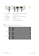
1-ph SNMP/Web plug-in adapter (P/N 1019070) LAN Front Panel – User Interface View RS-232 UPS UTP 10/100 Contact interface Active 1 Reset 3 2 4 5 • 1 – RJ45 Connector Ethernet connection, 10Base-T or 100Base-TX • 2 – LEDs Ref.
Rear View 6 1 3 7 • 1 – RJ45 Connector Ethernet connection, 10Base-T or 100Base-TX • 2 – LEDs Ref.
1.3 ARCHITECTURE ARCHITECTURE DIAGRAM Windows UPS Linux UNIX 10/100 Mbit/s UTP Ethernet Local console 1:1 RS232 Contact i/f NOTE: only required for configuration (1-ph plug-in version only) 1.4 SAFETY All maintenance and service work should be performed by qualified service personnel only. Please read carefully the Installation Manual before installing or operating the adapters. For more information on the UPS system, please refer to the applicable Installation and User Manual.
2 CONSOLE INTERFACE 2.1 INTRODUCTION The console interface provides a simple way to configure the SNMP/Web adapters through a command-line interface. Actually, the console interface provides a full set of commands, extending far beyond the adapter initial configuration and allowing access to all advanced functionalities.
2.1.2 Remote connection The console interface can also be accessed remotely from any computer on the same subnet using either Telnet or SSH (under the hypothesis that the relevant service is running and enabled for the selected user). TELNET Telnet provides basic user authentication. The SNMP/Web adapter uses the standard telnet port. To start a Telnet session and connect to the adapter: • Launch a telnet client (e.g.
• Most SSH clients display the host key fingerprint at the start of the session. Make sure the fingerprint shown matches the SNMP/Web adapter fingerprint (see Encryption section for details on figuring out the SSH fingerprint) • A login window should then be available in a few seconds. The default username (login) and password are ge and ge 2.1.3 Log-on User authentication requires inputting the username and password.
2.2 COMMAND LIST The various commands are split in different groups, depending on the involved functionality, and are listed here in accordance with their group classification. The command-line interface includes a command auto-completion feature. Normally, typing a command without any parameter displays usage information on the command. A help command is also available. Note that all commands are case-sensitive. 2.2.
2.2.2 Network command group The network command group allows to configure the board for communication over the network. Command Parameters Description showip Show the current network settings arp Show ARP table Define the network settings at boot-up (*) boot-method manual | dhcp | bootp manual static IP configuration, the device configuration (ref.
Setting the boot-method to manual has the side effect that manual-dns is also set to ON. Mind that the reverse is not true (setting boot-method to DHCP does not forced manual-dns to OFF). However, if the boot method is set through the quick network configuration menu, setting the boot-method to DHCP will also force manual-dns to OFF. Unlike network settings, the DNS settings may become immediately active. 2.2.
2.2.4 User command group The user command group is available only to the supervisor user, the only user who can perform user management. Command Parameters Description Change supervisor login name supername [name] showuser [name] New supervisor username NOTE: By default, the superuser is the only configured user with username and password set to ge and ge.
2.2.5 Service command group The service command group allows to enable/disable different services. Note that the local (serial) connection cannot be disabled.
2.2.6 Time command group The time command group allows to enable/disable different services. Note that the local (serial) connection cannot be disabled. Command Parameters showtime Description Show all configured time settings Enable/disable NTP client ntponoff on | off on off NTP client enabled NTP client disabled Define NTP server ntp-server [hostname] [hostname] hostname or IP-address of the NTP server NOTE: using hostnames requires DNS connection.
2.2.
2.2.8 Snmp command group The snmp command group allows to configure the SNMP Agent for UPS monitoring via SNMP and trap notification of UPS events and alarms: Command Parameters showsnmp Description Show detailed system information Set SNMP server listening port (*) snmpport [port] [port] SNMP port NOTE: Default SNMP port is 161.
2.2.9 Trap command group The trap command group allows to configure the trap sending functionality. With SNMP traps various systems can be notified in case of UPS events and alarms.
2.2.10 UPS command group The UPS command group allows monitoring and configuration of the managed UPS system. Command Parameters Description upsinfo (*) Show detailed UPS information upstest (*) Start/Stop UPS tests upscontrol (*) Control the UPS (1-ph/SP versions ONLY) upsconfig (*) Configure UPS parameters Set UPS attached device attacheddevice [device] alarmdelay [time] [device] Device which is powered/protected by the UPS NOTE: Maximum length 63 chars.
(*) By running these commands, an interactive menu is launched – follow the on-screen instructions. The menu also provide a complete on-line help section. NOTE: When using the local serial connection, make sure that the terminal emulation is set to VT-100, otherwise the interactive menu may not be rendered correctly. Caution! Some of these commands (particularly upscontrol and upsconfig) may inject commands and/or alter the UPS configuration with consequences on the UPS operation that may affect the load.
2.2.12 Events command group The events command group controls the alarm notification via traps and/or e-mail. Command Parameters showevents Description Show the alarm notification configuration Configure the alarm notification for a specific event event [row] [e-mail] [trap] [row] Alarm ID [e-mail] 0 = no e-mail notification for this alarm 1 = send e-mail on alarm (de)activation [trap] 0 = no trap sent for this alarm 1 = send trap on alarm (de)activation 2.2.
3 WEB INTERFACE 3.1 INTRODUCTION The SNMP/Web adapters provide a web interface by implementing an embedded web server. This interface allows to configure the adapter in order to monitor and manage the UPS. 3.1.1 Supported browsers The use of non-standard / deprecated HTML tags has been avoided in order to guarantee compatibility with the most commonly used browsers. Although the web page rendering may not be identical in different browsers, it should always be visually consistent.
3.1.4 Saving the settings Apart from some network parameters, most setting are immediately active. However, the adapter will revert to the last save settings at reboot. Therefore, in order to permanently modify the SNMP/Web adapter setting, remember to save the configuration after every change. 3.
3.3.2 Battery page The Battery page shows the following information. Parameter Name Description Battery Status The current status of the battery: 1 – unknown 2 – normal The remaining run-time on batteries is greater than the UPS low battery time (ref. UPS Config page) 3 – low The remaining run-time is less than or equal the UPS low battery time (ref.
3.3.3 UPS Status page The UPS status page shows the following information for each of the input / output / bypass lines.
3.3.6 UPS Test page This page presents allows to initiate a specific UPS test, and reports the status of the last performed test (if any). The page includes a table with clear explanation of the test result reading. For an explanation of the various test procedures please refer to the applicable UPS documentation. 3.3.7 UPS Control page (1-ph/SP units ONLY) The UPS control page mainly controls UPS shutdown and reboot behaviour.
3.4 SYSTEM SECTION 3.4.1 Network page Network configuration of the card – refer to the NETWORK CONFIGURATION chapter within this manual. Note that the settings on this page will only take effect after a reboot of the card. 3.4.2 Date&Time page Through this page it is possible to configure the adapter date and time settings.
3.4.5 Configuration page In this page, the SNMP/Web adapter configuration file is shown in a text area. The configuration file can be exported by pressing the Highlight button and copying the selected text (e.g. CTRL+C) to a separate application. 3.4.6 Upgrade page This page shall only be accessed when the SNMP/Web adapter SW is to be upgraded. Refer to the section for details on the SW upgrade process. NOTE: Use only GE officially released SW. Only perform the SW upgrade when requested to do so by GE. 3.
3.6 SMTP SECTION The SMTP page controls the e-mail notification functionality. 3.6.1 SMTP configuration page The basic SMTP settings are the following: Parameter Name Description SMTP Server Hostname or IP-address of the SMTP server Sender name The MAIL FROM field of the mail message Recipent e-mail address The RCPT TO field of the mail message If the SMTP server requires authentication, the following sections shall also be defined.
3.9 SAVE SECTION This section allows to save the current settings to non-volatile memory (Save) and/or to reboot the adapter (Reboot). Remember that the SNMP/Web adapter will revert to the last saved settings at reboot. Therefore, in order to permanently modify the settings the configuration must be saved. 3.10 USER SECTION This section offers access to the user management web page. Note that this page becomes operative only for the supervisor user (the only user enabled to perform user management).
4 SNMP AGENT The SNMP/web adapters implement an SNMP Agent providing access to OIDs according to the MIB structure, and may generate traps at the occurrence of specific events. This allows one or more NMSs (Network Management Systems) to monitor, manage and control the UPS. The SNMP Agent complies with the standard UPS-MIB as specified in RFC1628. Limited to the 3-ph SNMP/Web plug-in adapter, additional information is available with the GESingle and GEParallel MIBs.
OIDs ==== upsInput Group ==== upsInputLineBads upsInputNumLines upsInputFrequency upsInputVoltage upsInputCurrent upsInputTruePower ==== upsOutput Group ==== upsOutputSource upsOutputFrequecny upsOutputNumLines upsOutputVoltage upsOutputCurrent upsOutputPower upsOutputPercentLoad TRAPS & ALARMS UpsAlarmBypassBad UpsAlarmOutputOffAsRequested UpsAlarmUpsOffAsRequested UpsAlarmChargerFailed UpsAlarmUpsOutputOff UpsAlarmUpsSystemOff UpsAlarmFanFailure UpsAlarmFuseFailure UpsAlarmGeneralFault UpsAlarmDiagnostic
4.3 GE MIB OBJECTS GE provides private MIBs, which enhance the UPS information available over SNMP interface. These MIBs are only supported on 3-ph SNMP/Web plug-in adapter. Two different version of the GE private MIB exist: • GE Single MIB: to be used for monitoring of a 3-ph UPS is single unit configuration • GE Parallel MIB: to be used for monitoring of a 3-ph parallel UPS system The MIB structure is shown in the following picture.
upsInputVoltage upsInputCurrent upsInputTruePower upsInputVoltageMin [*] upsInputVoltageMax [*] ==== upsOutput Group ==== upsOutputSource upsOutputFrequecny upsOutputNumLines upsOutputVoltage upsOutputCurrent upsOutputPower upsOutputPercentLoad upsOutputPowerFactor [*] upsOutputPeakCurrent [*] upsOutputShareCurrent [*] upsAlarmTestInProgress upsAlarmReceptacleOff upsAlarmHighSpeedBusFailure [*] upsAlarmHighSpeedBusJACRCFailure [*] upsAlarmConnectivityBusFailure [*] upsAlarmHighSpeedBusJBCRCFailure [*] upsA
5 NETWORK CONFIGURATION The SNMP/Web adapter network interface is very flexible and can be configured for operation in various environments. This section details all possible network configuration combinations, while it is recommended to refer to Console/Web interface sections for the specific configuration commands / menus. 5.
5.3 DNS CONFIGURATION DNS configuration affects the SNMP/Web adapter ability to resolve symbolic hostnames to IP addresses, and may impact other functionality (such as e-mail sending, for example): The SNMP/Web adapters can be configured to automatically obtain DNS server address (e.g. Primary and Secondary DNS server as specified in the DHCP response). This is the defaults setting. Alternatively, the IP address of the DNS servers may be specified manually.
6 MULTI-SERVER NETWORK SHUTDOWN (RCCMD) The SNMP/Web adapters include a module for Multi-Server Network Shutdown. This module allows the configuration of a shutdown strategy for several servers powered by the UPS when the batteries are running low following a prolonged mains failure. 6.1 NETWORK SHUTDOWN WITH RCCMD RCCMD (Remote Console Command) is a mechanism that allows the execution of commands on remote systems. With the SNMP/Web adapters this mechanism is used to shutdown servers powered by the UPS.
Finally, it is possible to configure the actual condition that triggers the RCCMD Shutdown command: • After X minutes that the UPS is running on battery • At X minutes of estimated minutes remaining of battery autonomy • When the UPS signals a low battery condition Note that a low battery condition will force the shutdown of the configured RCCMD Clients regardless of the chosen shutdown condition. The configuration of the clients can be tested – the SNMP/Web adapter includes a Test function.
6.2 RCCMD CLIENT RELAY The maximum number of RCCMD Clients that can be managed by the SNMP/Web adapter is limited. In order to reach a higher number of RCCMD Clients, one or more of these clients can be configured to operate as relays. Basically, the RCCMD Client needs to be configured so that it will execute a batch or script file that issues more RCCMD Shutdown commands.
7 SECURITY As any other device connected to a network, the adapters are exposed to security threats. This section details the advanced security features provided by the SNMP/Web adapters. Users should use the information provided in this section to correctly configure the cards and implement all security features deemed appropriate to the installation environment. 7.
7.2 SERVICES (ACCESS METHODS) The table below lists the available services (access methods), highlighting the major security features for each interface. Interface Local console interface Remote console interface Access methods Serial cable Telnet SSH (Secure SHell) SNMP Agent SNMP File transfer FTP SFTP (SSH FTP) Web interface HTTP HTTPS (SSL) 7.
The fingerprint may be checked against the information provided by the SNMP/Web adapter to confirm to SSH server identity. On the console interface inject the ssh-fingerprint command. Below is a sample output of the ssh-fingerprint command: GEDE> ssh-fingerprint 1024 6e:07:31:58:16:91:ae:2e:43:6f:03:64:94:57:55:6d ssh_host_rsa_key.pub 1024 06:97:69:97:cd:93:1b:b6:29:ca:34:e5:8c:35:7c:6e ssh_host_dsa_key.pub 1024 d1:9b:50:13:b3:e3:98:8e:8c:76:49:14:be:21:ed:b3 ssh_host_key.
7.3.2 SSL Certificates HTTPS is not a protocol itself, but it actually refers to HTTP communication over SSL (Secure Sockets Layer) connection. HTTPS uses public-key cryptography to protect the communication. With HTTPS, the server sends back its identification in the form of a digital certificate. The certificate usually contains the server name, the trusted certificate authority (CA), and the server's public encryption key.
On the console interface inject the ssl-fingerprint command. Below is a sample output of the sslfingerprint command: GEDE> ssl-fingerprint MD5 Fingerprint=8F:A1:CE:8B:B3:04:E7:07:90:6D:02:77:6F:EE:9E:22 SHA1 Fingerprint=F5:D2:CA:27:BF:DA:98:31:39:6F:18:8C:C5:9C:BC:6C:D3:62:15:AC It can be seen that the thumbprint shown by the web browser (with thumbprint algorithm shown as sha1) matches the SHA1 fingerprint as shown by the ssl-fingerprint command.
7.4 CUSTOMER RESPONSIBILITY As shown above, the SNMP/Web adapters implement advanced security features. Nevertheless, achieving complete security protection requires the introduction of a comprehensive security program. This section lists some good practices in network security that customers are recommended to adopt. 7.4.1 Physical security Most of the security features would prove useless if physical access to the equipment is uncontrolled.
8 OTHER FUNCTIONALITIES 8.1 SYSTEM TIME The SNMP/Web adapter provides means to maintain the system time. Particularly, the adapter will maintain an internal clock when powered-up, while an RTC with battery back-up will hold date/time information when off (or during power-cycles). This system offers a sufficient accuracy in the short term. However, in the longer term the time drift may become significant. For best results it is recommended to configure the adapter for communication with an NTP server.
8.3.1 UPS Load Alert The SNMP/Web adapter monitors the UPS Output Percent Load and reports a UpsLoadAlert when the load drops of a defined percentage (the actual load step detected is also saved in the UPS log). This functionality warns the user that there has been a drop in the UPS load. This could indicate potential issues with the UPS load (fuse blown, breaker tripped, unit off, etc.). Per current implementation, the alert is only available for HTTP based monitoring.
9 MAINTENANCE 9.1 SOFTWARE UPGRADE The application software in the SNMP/Web adapter may be upgraded (please note that the upgrade procedure can be performed only by the supervisor and by rw users). The procedure to upgrade the software is described below: • Transfer the new software (gedeappXXX.
10 TROUBLESHOOTING 10.1 TROUBLESHOOTING UPS CONNECTION The SNMP/Web adapter front panel features a LED marked ‘UPS’. This LED should be OFF in normal conditions. If the LED is ON then there is a problem in the communication with the UPS. NOTE: It may take up to one minute for the adapter to synchronise the communication with the UPS. Also, the SNMP/Web adapter will signal a Communication Lost alarm if communication with the UPS is lost and cannot be re-established. 10.1.
10.3 TROUBLESHOOTING NETWORK CONNECTION When experiencing difficulties in the network access to the card follow the flowchart below to identify the root-cause of the problem and implement proper corrective actions.
10.4 TROUBLESHOOTING WEB ACCESS Refer to the following table for troubleshooting most common problems in accessing the embedded web interface. Please note that proper browser configuration is responsibility of the user – this section aims to give guidance to understanding the common access problems and browser errors.
10.6 TROUBLESHOOTING E-MAIL NOTIFICATION (SMTP) When e-mail notification via SMTP is configured and enabled, the SNMP/Web adapter will notify the selected recipients upon UPS alarm activation / deactivation. If problems are experienced with this functionality, follow the flowchart below to identify the root-cause of the problem and implement proper corrective actions. Please note that proper configuration of the SNMP/Web adapter and the SMTP server set-up and configuration are responsibility of the user.
10.7 TROUBLESHOOTING NETWORK SHUTDOWN When experiencing difficulties with the Network Shutdown functionality (RCCMD), there are a few diagnostic tools that can be used. The first step is to ensure that the SNMP/Web adapter can reach the RCCMD Client. The actual network connectivity between the two nodes can be checked with the usual ping command. However, the actual RCCMD communication and related configuration can also be tested.
11 CUSTOMER SUPPORT 11.1 FIRST LINE SUPPORT Please contact your local GE distributor for problems with the installation of the product or its use. 11.2 INTERNET On-line support available on request (Internet access required). 11.3 WWW SERVER We have a WWW server running at www.gedigitalenergy.com With your favourite web browser you can access the latest information from GE, and download updates and manuals for this product. Modifications reserved OPM_CNT_SNM_BAS_CRD_1GB_V012.