User Manual Kinsey LED Ceiling Fan 1.12 m (44 in.) MODEL: 20444 Brushed Nickel MODEL: 20505 Bronze MODEL: 20611 White 120V 60Hz, MADE IN CHINA Customer Assistance 1-866-885-4649 customerservice@skyplug.com Contact a qualified electrician or call the Customer Care Service Team at 1-866-885-4649 Customer Service hours of operation are 9:00AM-5:00PM EST -Monday-Friday customerservice@skyplug.com Register your GE Branded fan for warranty coverage on www.gelightingandfans.
Safety Rules READ AND SAVE THESE INSTRUCTIONS 1. To reduce the risk of electric shock, ensure electricity has been turned off at the circuit breaker or fuse box before beginning. 2. All electrical connections must be made in accordance with local codes, ordinances and/or the National Electric Code. Electrical installation should be performed by a qualified licensed electrician. 3. WARNING: to reduce the risk of electrical shock or fire, do not use this fan with any solid-state fan speed control device.
SAFETY TIPS 1. Before working on a circuit , go to the main service panel and remove the fuse or turn off the breaker that controls that circuit . 2. Tape a sign to the panel warning others to leave the circuit alone while you work. 3. Before touching any wire, use a voltage tester to make sure it’s not live. 4. Whenever you check for voltage in a receptacle, check both outlets; each may be controlled by a separate wiring circuit . 5. When replacing fuses, turn off the main power first .
Tools Needed (Not Supplied) Required Flathead Screwdriver (#1 screwhead recommended) Step Ladder 3 Philips Screwdriver Wire Stripper Safety Glasses Soft Cloth
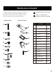
Hardware Included ATTENTION: Parts are not to scale. Carefully unpack and identify each part to make sure you have everything ready for installation. Lay out each part on a clean area such as a table or floor. Check to make sure you have the following: Hardware Bag NOTE: +1 = Extra quantity supplied for future use if needed.
Package Contents Carefully unpack and identify each part to make sure you have everything ready for installation. Lay out each part on a clean area such as a table or floor. Check to make sure you have the following: ATTENTION: parts are not to scale.
Fan Installation Drawing SkyReceptacle SkyPlug Receptacle Slot Mounting Screw Cover Plate Receiver Push Lever Register your GE Branded fan for warranty coverage on www.gelightingandfans.
SkyReceptacle Typical Wire Configurations TYPICAL WIRE CONFIGURATIONS: IMPORTANT: For remote control fans, L1 is the only active live /hot terminal. The hot/live wire from house supply must be inserted into L1 terminal for the fan to operate.
SkyReceptacle Installation Important: Always install SkyReceptacle with rubber washers to avoid a gap or uneven surface, and to ensure proper placement of receptacle on the ceiling. 0-1.5mm Gap 0-1.5mm 4mm rubber washer (pre-installed) If your box is flush with the ceiling, or recessed less than 1.5mm, install with 4mm rubber washers. 4mm rubber washer 1.5-3mm 7mm rubber washer 1.5-3mm Gap 7mm rubber washer If your box is recessed between 1.5mm and 3mm, use 7mm rubber washers.
SkyReceptacle Installation 1 1/2"/12.7mm OK Not OK Not OK 2 Outlet Box (not Supplied) Terminal’s Bottom view on Sky Receptacle Sky Receptacle Insert wires into terminal, tighten screw to secure wires. Screw torque 6.3 lb-in. 9 Note : If you do not have standard wiring configurations, please contact a qualified electrician, or call customer service 1-866-885-4649.
SkyReceptacle Installation 3 Rubber Washer Using the rubber washer when installing receptacle ensures proper placement of the receptacle on the ceiling. We recommend using the rubber washers in all installations.
Fan Installation There are two options to install the fan: 1) ASSEMBLY ON CEILING - follow steps 4 - 12. 2) ASSEMBLE ON FLOOR - follow steps 9 - 12 to first assemble blades and light kit to fan while on floor, and then steps 4 - 8 to install fully assembled fan onto ceiling. TIP: Practice attaching the fan motor to ceiling (step 6A-E) before installing fan blades and light kit. To release fan from ceiling, follow instructions on page 20. 4 Slide down trim ring from canopy.
Fan Installation 6A Lift fan, press up on push lever. 6B IMPORTANT: For proper moun ng, the SkyPlug and SkyReceptacle need to be lined up in a “+” formation. Line up SkyPlug to SkyReceptacle mounted in ceiling. Insert SkyPlug into SkyReceptacle (Keep push lever pushed up while inserting).
Fan Installation 6C IMPORTANT : SkyPlug must be fully engaged into SkyReceptacle. Once plug is fully inserted, let go of push lever while supporting fan. 6D “Click” sound IMPORTANT : Push lever must be in DOWN position once installed. Push up on fan to lock plug into receptacle (listen for locking “click”). 6E 90 Turn fan to the right (counter clockwise) to engage into slots and activate the final locking mechanism.
Fan Installation 7 Once installed, tighten all 4 screws. 8 Reinstall the trim ring, being careful not to depress the push lever. 9 Install blades.
Fan Installation 10 Note: Loosen 2 and remove 1 of the 3 mounting plate screws located at the bottom of motor assembly. Remove 1 Loosen 2 Install Mounting plate. 11 Remove 1 Loosen 2 Note: Loosen 2 and remove 1 of the 3 light kit mounting screws on the mounting plate. Install LED Light kit . 12 Install shade-turn to secure. 15 WARNING: Make sure to fully secure the glass shade in place by turning the shade clockwise (to the right) until it is locked in place and can no longer be rotated.
Installing the Transmitter Holder Select a location to install your transmitter holder. Attach the transmitter holder with the two short wood screws provided. Fan Operation Reverse Function Summer Reverse Switch Winter Fan Operation Using Standard Wall Switches -Only one standard wall switch can be used to turn the fan ON/OFF. The fan light and fan speed must be controlled with the included remote control. -An optional remote control holder is included, which can be mounted near the wall switch.
Remote Control Unlock Position Operate Fan Using Transmitter Code Pre-set by Factory ( Keep Switch Placed In Unlock Position ) Step 1. Restore power to ceiling fan. Step 2. Install two 1.5-volt AAA batteries provided. Step 3. Press the “ ” button located on the front of the transmitter to operate the fan. Step 4. Press the “ ” button to operate the light . A dimmer feature is provided on the light . Press all the way down to get maximum light .
Remote Control IMPORTANT: If the remote control is not operating correctly, please follow the steps on page 17 for pairing. Use the corner of the battery cover to press the "Sync" button for syncing function. REMOTE FUNCTIONS Operation indicator Low speed Medium speed High speed Power ON/OFF Delays the light turning off for approximately 5 seconds, enabling you to exit your room before the light turns off completely. Controls the light and brightness setting.
Blade Wobble Balancing B Not OK D C Y X X - Y< 3mm / ⅛in. X - Y >3mm / ⅛in.
Maintenance PRODUCT MAINTENANCE Suggestions to help maintain your fan Because of the fan’s natural movement , some connections may become loose. Check the support connections, brackets, and blade attachments twice a year. Make sure they are secure. (It is not necessary to remove fan from ceiling). Cleaning the fan Clean your fan periodically to help maintain its new appearance over the years. Use only a soft brush or lint-free cloth to avoid scratching the finish.
Troubleshooting CAUTION: Switch off power supply before carrying out any of these checks. 1.SkyPlug will not insert into SkyReceptacle: -Add rubber washers between J-box and SkyReceptacle. See Page 10 step 3. -Make sure you removed the disposable rubber inserts (page 11). -Watch installation video on www.gelightingandfans.com 2.Fan will not start: -Check main and branch circuit fuses or breakers. -Check to make sure the wall switch is in the ON position. -Check remote control operation. 3.
Manual del Usuario Ventilador de techo con iluminación LED Kinsey 1,12 m (44 pulgadas) Modelo: 20444 Niquel Pulido Modelo: 20505 Bronce Modelo: 20611 Blanco 120 V 60 Hz, HECHO EN CHINA Atención al cliente 1-866-885-4649 customerservice@skyplug.com Contacte a un electricista calificado o llame al Equipo del Servicio al Cliente Horas de operación del Servicio al Cliente son de 9:00AM-5:00PM Hora Estándar del Este-Lunes-Viernes Customerservice@skyplug.
Para su seguridad LEA Y GUARDE ESTAS INSTRUCCIONES 1. Para reducir el riesgo de descarga eléctrica, asegúrese de que la electricidad se haya apagado en el disyuntor o caja de fusibles antes de comenzar. 2. Todo el cableado debe ajustarse a la última edicion del Código Eléctrico Nacional “ANSI/NFPA 70” y los códigos eléctricos locales. Un electricista calificado y certificado debe realizar la instalación eléctrica. 3.
Guías Básicas Para Trabajar Con Electricidad Consejos de Seguridad 1. Antes de trabajar en un circuito, vaya al panel de servicio principal y retire el fusible o active el disyuntor que controla ese circuito. 2. Pegue una señal en el panel que advierta a otras personas que se alejen del circuito mientras usted trabaja. 3. Antes de tocar cualquier cable, use un voltímetro para asegurarse de que no esté bajo tensión. 4. Al comprobar el voltaje en un receptáculo, compruebe ambas salidas.
Herramientas Necesarias (No Suministradas) Requerido Destornillador de Cabeza Plana (Se recomienda un Destornillador #1) Escalera 3 Destornillador Philips Pelador de Cables Gafas de Seguridad Paño suave
Herramientas Incluidas Desempaque cuidadosamente e identi que cada pieza para asegurarse de que esté todo listo para la instalación. Coloque cada pieza sobre una super cie despejada, como una mesa o el piso. Veri que que tenga lo siguiente: Accessorios de ferretería ATENCIÓN: Las piezas no están a escala.
Contenido del Paquete Cuidadosamente desempaque e identifique cada pieza para asegurarse que tiene todo listo para la instalación. Coloque todas las piezas en una superficie limpia y plana como una mesa o el suelo. Asegúrese que tiene lo siguiente: Accesorios de jación ATENCIÓN: Las piezas no están a escala.
Esquema de instalación del ventilador Revise las instrucciones importantes de seguridad antes de proceder con la instalación.
Configuraciones Típicas de Cableado del Receptáculo Sky CONFIGURACIONES TÍPICAS DE CABLEADO: IMPORTANTE: Para ventiladores con control remoto, L1 es el único terminal activo. El cable con corriente de suministro de la casa debe insertarse en la terminal L1 para que el ventilador funcione. Negro (Vivo) Blanco DIAGRAMA DE CABLEADO #1 Configuraciones Típicas de Cableado para 1 Interruptor de Pared.
Instalación del Receptáculo Sky Importante: Siempre use las arandelas de goma cuando este instalando el receptor. Esto ayudara a asegurar que el ventilador se conecte correctamente. Espacio de 0-1,5mm 0-1.5mm Arandela de goma de 4mm (Pre-ensamblado) Si su caja esta al ras con el techo o empotrada a menos de 1.5mm, instale las arandelas de goma de 4mm. Arandela de goma de 4mm 1.5-3mm Arandela de goma de 7mm Espacio de 1.5-3mm Arandela de goma de 7mm Si su caja esta empotrada entre 1.
Instalación del Receptáculo Sky 1 1/2 pulgadas/12,7 mm OK No OK No OK 2 Caja Eléctrica (no suministrada) Vista de debajo de los terminales del receptáculo Sky Receptáculo Sky Inserte los cables en los terminales, apriete los tornillos para asegurar los cables. Fuerza de giro 6.3 libras-pulgada. 9 Nota: Si usted no tiene una configuración estándar en su cableado, por favor contacte un electricista o llame a Servicio al Cliente al 1-866-885-4649.
Instalación del Receptáculo Sky 3 Arandela de Goma Usando la arandela de goma cuando instale los receptáculos permite una colocación apropiada del receptáculo en el techo. Recomendamos el uso de las arandelas de goma en todas las instalaciones.
Instalación del ventilador Hay dos opciones para instalar su ventilador: 1) Para ensamblar en el techo siga los pasos 4 -12 2) Para ensamblar en el piso – siga los pasos 9-12 para primero ensamblar las aspas y el kit de luz al ventilador mientras esta en el piso y luego los pasos 4-8 para instalar el ventilador ensamblado al techo. TIP: Primero practique instalando el motor del ventilador al techo (Paso 6A-E) antes de ensamblar las aspas y el kit de luz al motor.
Instalación del ventilador 6A Levante el ventilador y presione hacia arriba la palanca de empuje. 6B IMPORTANTE: Para un montaje correcto, SkyPlug y SkyReceptacle deben estar alineados en forma de “+”. Alinee Skyplug con el SkyReceptacle montado en el techo. Introduzca Skyplug en el SkyReceptacle (mantenga la palanca de empuje hacia arriba durante la inserción).
Instalación del ventilador 6C IMPORTANTE: Skyplug debe estar totalmente acoplado en el receptáculo Una vez que el dispositivo esté totalmente introducido, suelte la palanca de empuje mientras sostiene el ventilador. 6D Sonido de «clic» IMPORTANTE : La palanca de empuje debe estar en la posición baja una vez completada la instalación Empuje hacia arriba el ventilador para bloquear el dispositivo en el receptáculo (hasta escuchar el «clic» de bloqueo).
Instalación del ventilador 7 Una vez instalado, apriete los 4 tornillos. 8 Reinstale el anillo del borde nuevamente, teniendo cuidado de no presionar la palanca de presión. 9 Instale las aspas del ventilador.
Instalación del ventilador 10 Nota: Afloje 2 y retire 1 de los 3 tornillos de la placa de montaje ubicados en la parte inferior del motor primero. Retire 1 Afloje 2 Instale el plato de montaje. 11 Retire 1 Afloje 2 Nota: Afloje 2 y retire 1 de los 3 tornillos de montaje del kit de luz en la placa de montaje primero. Instale el conjunto de luz LED. 12 Instale la campana, gírela hasta que este segura.
Instalación del Soporte de Transmisor Seleccione una ubicación para instalar el soporte del transmisor. Fije el soporte del transmisor con los dos tornillos de madera suministrados. Operacion del Ventilador Función de Reversa Verano Interruptor de Reversa Invierno Funcionamiento del Ventilador utilizando interruptores de pared estándar -Solo un interruptor de pared estándar se puede usar para prender y apagar el ventilador.
Control Remoto Posición de desbloqueo Opere el Ventilador Usando el Código de Transmisión Pre Instalado de Fábrica ( Mantener el interruptor colocado en posición de desbloqueo ) Paso 1. Restablezca la electricidad del ventilador. Paso 2. Instale dos baterías AAA de 1,5 -vatios provistas. Paso 3. Presione el botón “ ” localizado en la parte delantera del transmisor para operar el ventilador. Paso 4. Presione el botón “ ” para operar la luz. Esta luz viene equipada con regulacion de intensidad ajustable.
Control Remoto FUNCIONES DEL CONTROL REMOTO IMPORTANTE: Si el control remoto no funciona correctamente, favor de seguir las instrucciones en la página 17 para el emparejamiento del interruptor. Use la esquina de la cubierta de las baterías para presionar el botón "Sync" para la función de emparejamiento.
Balanceo de las aspas B No OK A Y X X - Y < 3mm / ⅛ pulgadas X - Y >3mm / ⅛ pulgadas OK OK 19 D C OK No OK
Mantenimiento MANTENIMIENTO DEL PRODUCTO * Sugerencias para ayudarle a mantener su ventilador * Producto del movimiento natural del ventilador, algunas de las conexiones se podrán aflojar. Revise los suportes de las conexiones, soportes del ventilador y accesorios de las aspas dos veces al año. Asegúrese que estén seguros. (No es necesario remover el ventilador del techo). * Limpieza del ventilador * Limpie su ventilador periódicamente para ayudar a mantener su nueva apariencia al pasar de los años.
Solución de Problemas CUIDADO: Apague la electricidad antes de realizar los siguientes procedimientos 1.EL Skyplug no se insertará en el Receptor: -Agregue arandelas de goma entre el J-box y el Receptor. Vea la página 10 paso 3. -Asegúrese de quitar las inserciones de goma desechables (página 11). -Ver video de instalación en www.gelightingandfans.com 2. El ventilador no enciende: -Revise los fusibles de circuitos e interruptores automáticos principales o periféricos.