Installation Instructions Over the Range Microwave Oven JVM3162 JNM3163 Questions? Call 800.GE.CARES (800.432.2737) or Visit our Website at: GEAppliances.com BEFORE YOU BEGIN Read these instructions completely and carefully. • IMPORTANT – Save these instructions for local inspector’s use. • IMPORTANT – Observe all governing codes and ordinances. • Note to Installer – Be sure to leave these instructions with the Consumer. • • • • • Note to Consumer – Keep these instructions for future reference.
Installation Instructions C CONTENTS Recirculating ................................................. 19–22 General information Attach Mounting Plate to Wall ................ 19 Important Safety Instructions........................................ 3 Preparation of Top Cabinet...................... 19 Electrical Requirements .................................................. 3 Adapting Blower for Recirculation ........................................20, 21 Hood Exhaust ...............................
Installation Instructions IMPORTANT SAFETY INSTRUCTIONS You should have the wall receptacle and circuit checked by a qualified electrician to make sure the receptacle is properly grounded. This product requires a three-prong grounded outlet. The installer must perform a ground continuity check on the power outlet box before beginning the installation to insure that the outlet box is properly grounded.
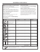
Installation Instructions HOOD EXHAUST NOTE: Read these next two pages only if you plan to vent your exhaust to the outside. If you plan to recirculate the air back into the room, proceed to page 6. OUTSIDE TOP EXHAUST (EXAMPLE ONLY) The following chart describes an example of one possible ductwork installation. EQUIVALENT LENGTH x DUCT PIECES NUMBER USED = EQUIVALENT LENGTH Roof Cap 24 Ft. x (1) = 24 Ft. 12 Ft. Straight Duct (6” Round) 12 Ft. x (1) = 12 Ft.
Installation Instructions Maximum duct length: NOTE: If you need to install ducts, note that the total duct length of 3¼”x 10” rectangular or 6” diameter round duct should not exceed 120 equivalent feet. Outside ventilation requires a HOOD EXHAUST DUCT. Read the following carefully. NOTE: It is important that venting be installed using the most direct route and with as few elbows as possible. This ensures clear venting of exhaust and helps prevent blockages.
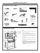
Installation Instructions PARTS INCLUDED '$0$*( ² 6+,30(17 INSTALLATION ADDITIONAL PARTS • If the unit is damaged in shipment, return the unit PART to the store in which it was bought for repair or replacement. • If the unit is damaged by the customer, repair or replacement is the responsibility of the customer. • If the unit is damaged by the installer (if other than the customer), repair or replacement must be made by arrangement between customer and installer.
Installation Instructions TOOLS YOU WILL NEED Ruler or tape measure and straight edge Pencil Carpenter square (optional) # 1 and #2 Phillips screwdriver Tin snips (for cutting damper, if required) Scissors (to cut template, if necessary) Electric drill with 1/16”, 7/16”, 3/8”, 1/2”and 5/8” drill bits Gloves Saw (saber, hole or keyhole) Filler blocks or scrap wood pieces, if needed for top cabinet spacing (used on recessed bottom cabinet installations only) Stud finder or Hammer (optional) Safety go
Installation Instructions 1 PLACEMENT OF THE MOUNTING PLATE A. REMOVING THE OVEN FROM 7+( &$5721 5(029,1* 7+( MOUNTING PLATE B. FINDING THE WALL STUDS 1 Remove the turntable, installation instructions, filters, exhaust adaptor, damper, shelf and the small hardware bag. Do not remove the foam packing protecting the front of the oven. Wall Studs 2 Fold back all 4 carton flaps fully against carton sides. Then carefully roll the oven and carton over onto the top side.
Installation Instructions C. DETERMINING WALL PLATE LOCATION UNDER YOUR CABINET Plate position – beneath framed recessed cabinet bottom Plate position – beneath flat bottom cabinet Mounting Plate Tabs Touching the Cabinet Bottom Mounting Plate Tabs Touching the Back Frame 30” to Cooktop At least 30”, up to 36” Plate position – beneath recessed bottom cabinet with front overhang Your cabinets may have decorative trim that interferes with the oven installation.
Installation Instructions D. ALIGNING THE WALL PLATE Hole B Draw a Vertical Line on Wall from Center of Top Cabinet Hole A Hole C Hole D Area E NOTE: Appearance and shape of the mounting plate may vary from your model. CAUTION: Wear gloves to avoid cutting fingers on sharp edges. 1 Draw a vertical line on the wall at the center of the 30” wide space. 2 Use the mounting plate as the template for the rear wall.
Installation Instructions 2 INSTALLATION TYPES (Choose A, B or C) NOTE: This oven is shipped assembled for Outside Top Exhaust (except for non-vented models). Select the type of ventilation required for your installation and proceed to that section. This oven is designed for adaptation to the following three types of ventilation: A. Outside Top Exhaust (Vertical Duct) B. Outside Back Exhaust (Horizontal Duct) C.
Installation Instructions A OUTSIDE TOP EXHAUST (Vertical Duct) INSTALLATION OVERVIEW A1. Attach Mounting Plate to Wall A2. Prepare Top Cabinet A3. Install Adapter A4. Mount Oven A5. Adjust Exhaust Adaptor A6. Connect Ductwork To use toggle bolts: A1.
Installation Instructions A4. MOUNT THE OVEN A2. USE TOP CABINET TEMPLATE FOR PREPARATION OF TOP CABINET You need to drill holes for the top support screws, a hole large enough for the power cord to fit through, and a cutout large enough for the exhaust adaptor. FOR EASIER INSTALLATION AND PERSONAL SAFETY, WE RECOMMEND THAT TWO PEOPLE INSTALL THIS OVEN. IMPORTANT: Do not grip or use handle during installation.
Installation Instructions A4. MOUNT THE OVEN (continued) A5. ADJUST THE EXHAUST ADAPTOR Cabinet Front Open the top cabinet and adjust the exhaust adaptor to connect to the house duct. Cabinet Bottom Shelf Filler Block Equivalent to Depth of Cabinet Recess Damper Back of Oven Self-Aligning Screw Oven Top 3 Attach the oven to the top cabinet by inserting 2 self-aligning screws through outer top cabinet holes. Turn two full turns on each screw. Be sure to keep power cord tight.
Installation Instructions B OUTSIDE BACK EXHAUST (Horizontal Duct) INSTALLATION OVERVIEW B1. Prepare Rear Wall B2. Attach Exhaust Adaptor to Wall Plate B3. Attach Mounting Plate to Wall B4. Prepare Top Cabinet B5. Adjust Blower B6. Mount the Oven B1. PREPARING THE REAR WALL FOR OUTSIDE BACK EXHAUST B2. ATTACH THE EXHAUST ADAPTOR TO THE OVEN REAR PANEL You need to cut an opening in the rear wall for outside exhaust. 1 Unscrew and remove the exhaust adaptor assembly from the top of the oven.
Installation Instructions B4. USE TOP CABINET TEMPLATE FOR PREPARATION OF TOP CABINET B3. ATTACH THE MOUNTING PLATE TO THE WALL You need to drill holes for the top support screws and a hole large enough for the power cord to fit through. Attach the plate to the wall using toggle bolts. At least one wood screw must be used to attach the plate to a wall stud. 1 Remove the toggle wings from the bolts.
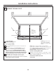
Installation Instructions B5. ADAPTING BLOWER FOR OUTSIDE BACK EXHAUST 5 Place the blower unit back into the opening. AFTER: Fan Blade Openings Facing Back 1 Remove the two screws that hold the blower plate and remove the screw holding the blower motor to the oven. Slide blower plate from under its retaining flange. Retaining Flange Blower Plate CAUTION: Do not pull or stretch the blower unit wiring. Make sure the wires are not pinched.
Installation Instructions Cabinet Front B6. MOUNT THE OVEN Cabinet Bottom Shelf Filler Block Equivalent to Depth of Cabinet Recess Self-Aligning Screw FOR EASIER INSTALLATION AND PERSONAL SAFETY, WE RECOMMEND THAT TWO PEOPLE INSTALL THIS OVEN. Oven Top IMPORTANT: Do not grip or use handle during installation. 3 Attach the oven to the top cabinet by inserting 2 self-aligning screws through outer top cabinet holes. Turn two full turns on each screw. Be sure to keep power cord tight.
Installation Instructions C RECIRCULATING (Non-Vented Ductless) INSTALLATION OVERVIEW C1. Attach Mounting Plate to Wall C2. Prepare Top Cabinet C3. Adjust Blower C4. Mount the Oven C5. Install Charcoal Filter 3 Place the mounting plate against the wall and insert the toggle wings into the holes in the wall to mount the plate.
Installation Instructions C3. ADAPTING BLOWER FOR RECIRCULATION 4 Roll the blower unit 90° so that fan blade openings are facing toward the front of the oven. BEFORE: Fan Blade Openings Facing Up NOTE: The exhaust adaptor with damper is not needed for recirculating models. You may want to save them for possible future use. 1 Remove and save screws that hold blower plate and blower unit to the oven.
Installation Instructions C3. ADAPTING BLOWER FOR RECIRCULATION (continued) NOTE: When mounting the oven, thread power cord through hole in bottom of top cabinet. Keep it tight throughout Steps 1–3. Do not pinch cord or lift oven by pulling cord. 5 Place the blower unit back into the opening. CAUTION: Do not pull or stretch the blower unit wiring. Make sure the wires are not pinched. 1 Lift oven, tilt it forward and hook slots at back bottom edge onto two lower tabs of mounting plate.
Installation Instructions C4. MOUNT THE OVEN (continued) C5. WHEN REPLACING THE CHARCOAL FILTER If the model is not vented to the outside, the air will be recirculated through a disposable charcoal filter that helps remove smoke and odors. 3 Attach the oven to the top cabinet by inserting 2 self-aligning screws through outer top cabinet holes. Turn two full turns on each screw. Be sure to keep power cord tight. Be careful not to pinch the cord, especially when mounting flush to bottom of cabinet.
Installation Instructions BEFORE YOU USE YOUR OVEN 1. Make sure the oven has been installed according to instructions. 6. Read the Owner’s Manual. 2. Remove all packing material from the oven. 7. KEEP INSTALLATION INSTRUCTIONS FOR THE LOCAL INSPECTOR’S USE. 3. Install turntable and wheeled ring in cavity. 4. Replace house fuse or turn breaker back on. 5. Plug power cord into a dedicated 15 to 20 amp electrical outlet.
Printed in China
Instrucciones de instalación Horno Microondas Horno para colocar Sobre encima delalaCocina estufa JVM3162 JNM3163 ¿Preguntas? Llame 800-GE-CARES (800-432-2737) o visite nuestra página en la red en: GEAppliances.com ANTES DE EMPEZAR Lea estas instrucciones completa y cuidadosamente. • • IMPORTANTE – Guarde estas instrucciones para el uso del inspector local. IMPORTANTE – Cumpla con todos los códigos y ordenanzas gubernamentales.
Instrucciones de instalación C Recirculación ..................................................... 19–22 CONTENIDO Cómo adherir la placa de montaje a la pared .........................................................19 Información general Instrucciones de seguridad importantes..................... 3 Cómo preparar el gabinete superior.............19 Requisitos eléctricos ........................................................ 3 Campana de escape ....................................................
Instrucciones de instalación INSTRUCCIONES DE SEGURIDAD IMPORTANTES Deberá hacer que un técnico calificado inspeccione el tomacorriente de pared y el circuito para asegurarse de que el tomacorriente esté conectado a tierra de manera apropiada. Este producto requiere un tomacorriente eléctrico de tres patas conectado a tierra.
Instrucciones de instalación CAMPANA DE ESCAPE NOTA: Lea las siguientes dos páginas solamente si planea ventilar el escape hacia el exterior. Si por el contrario planea recircular el aire de vuelta hacia el salón, continúe en la página 30. ESCAPE SUPERIOR EXTERNO (EJEMPLO SOLAMENTE) La siguiente tabla describe un ejemplo de una posible instalación de red de conductos.
Instrucciones de instalación Longitud máxima del conducto: NOTA: Si usted necesita instalar conductos, tenga pendiente que la longitud total del conducto rectangular de 31/4” x 10” o el conducto redondo de 6” de diámetro no debe sobrepasar 120 pies equivalentes. La ventilación externa requiere un CONDUCTO DE CAMPANA DE ESCAPE. Lea lo siguiente cuidadosamente. NOTA: Es importante que la ventilación sea instalada usando la ruta más directa y con la menor cantidad de codos posible.
Instrucciones de instalación PARTES INCLUIDAS DAÑOS – ENVÍO / INSTALACIÓN PARTES ADICIONALES • Si la unidad se daña durante el envío, devuelva PARTE la unidad al almacén donde la adquirió para su reparación o reemplazo. • Si el cliente daña la unidad, la reparación o el reemplazo es responsabilidad del cliente. • Si el instalador daña la unidad (si no es el cliente), la reparación o reemplazo se debe hacer por medio de un arreglo entre el cliente y el instalador.
Instrucciones de instalación HERRAMIENTAS QUE NECESITARÁ Regla recta y cinta métrica Lápiz Destornilladores de estrella # 1 y # 2 Tijeras para cortar latón (para cortar el regulador de tiro, si es necesario) Tijeras (para cortar la plantilla, si es necesario) Taladro eléctrico con brocas de 3/16", 7/16", 3/8", 1/2" y 5/8" Guantes Detector de postes de viga o un martillo (opcional) Sierra (de sable, agujero, o de ojo de cerradura) Gafas de seguridad Nivel Escuadra de carpintero (opcional) Bloques
Instrucciones de instalación 1 CÓMO COLOCAR EL PLATO DE MONTAJE A. CÓMO REMOVER EL HORNO DEL EMBALAJE / CÓMO REMOVER EL PLATO DE MONTAJE B. CÓMO ENCONTRAR LOS POSTES DE VIGA EN LA PARED 1 Remueva la caja que contiene las instrucciones de instalación, los filtros, el adaptador de escape, el regulador de tiro, estante y la pequeña bolsa con los elementos de instalación. No remueva la espuma de poliestireno que protege el frente del horno.
Instrucciones de instalación C. C.
Instrucciones de instalación D. CÓMO ALINEAR EL PLATO DE MONTAJE SOBRE LA PARED Trace une línea vertical en la pared a partir del centro del gabinete superior Agujero A Agujero B Agujero C Area E Agujero D PRECAUCIÓN: Use guantes de protección para evitar cortaduras en sus dedos con los extremos filosos. 1 Trace una línea vertical en la pared en el centro del espacio de 30” de ancho. 2 Use el plato de montaje como la plantilla para la pared posterior.
Instrucciones de instalación 2 TIPOS DE INSTALACIÓN (Escoja A, B o C) NOTA: Este horno es enviado ya ensamblado para un escape superior exterior (excepto para los modelos sin ventilación). Seleccione el tipo de ventilación requerido para su instalación y proceda a tal sección. Este horno está diseñado para adaptarse a los siguientes tres tipos de ventilación: A. Escape superior exterior (Conducto vertical) B. Escape posterior exterior (Conducto horizontal) C.
Instrucciones de instalación A ESCAPE SUPERIOR EXTERIOR (Conducto vertical) PERSPECTIVA GENERAL DE LA INSTALACIÓN A1. Como adherir el plato de montaje a la pared A2. Prepare el gabinete superior A3. Instale el adaptador A4. Monte el horno A5. Ajuste el adaptador de escape A6. Conecte el conducto Para usar los tornillos basculantes: A1.
Instrucciones de instalación A2. USE LA PLANTILLA DEL GABINETE SUPERIOR PARA LA PREPARACIÓN DEL GABINETE A4. CÓMO MONTAR EL HORNO Deberá perforar agujeros para los tornillos de apoyo superiores, un agujero suficientemente grande para que el cable eléctrico quepa, y un recorte lo suficientemente grande como para que el adaptador de escape pueda ser introducido. PARA OBTENER UNA INSTALACIÓN MÁS FÁCIL Y EN POS DE LA SEGURIDAD PERSONAL, SE RECOMIENDA QUE DOS PERSONAS INSTALEN ESTE HORNO.
Instrucciones de instalación A4. CÓMO MONTAR EL HORNO A5. CÓMO AJUSTAR EL ADAPTADOR DE ESCAPE (continuación) Frente del gabinete Abra el gabinete superior y ajuste el adaptador de escape para conectarlo al conducto de la casa.
Instrucciones de instalación B ESCAPE POSTERIOR EXTERNO (Conducto horizontal) PERSPECTIVA GENERAL DE LA INSTALACIÓN B1. Prepare la pared posterior B2. Como adherir el adaptador de escape al plato de montaje B3. Pegue el plato de montaje a la pared B4. Prepare el gabinete superior B5. Ajuste el calefactor B6. Monte el horno B1. CÓMO PREPARAR LA PARED POSTERIOR PARA EL ESCAPE POSTERIOR B2.
Instrucciones de instalación B4. USE LA PLANTILLA DEL GABINETE SUPERIOR PARA PREPARAR EL GABINETE SUPERIOR B3. CÓMO ADHERIR EL PLATO DE MONTAJE A LA PARED Necesita perforar agujeros para los tornillos de apoyo superiores y un agujero suficientemente grande para que el cable eléctrico quepa. Pegue el plato a la pared usando los tornillos basculantes. Por lo menos un tornillo de madera debe ser usado para pegar el plato al poste de viga de la pared. 1 Remueva las mariposas de los tornillos.
Instrucciones de instalación B5. CÓMO ADAPTAR EL CALEFACTOR PARA EL ESCAPE POSTERIOR EXTERNO 5 Coloque la unidad del calefactor de nuevo en la abertura. DESPUES: Las aberturas de la paleta del ventilador están orientadas hacia atrás 1 Remueva los dos tornillos que sostienen el plato del calefactor y el tornillo que sostiene el motor del calefactor en el horno. Deslice el plato del calefactor de abajo de su reborde de retención.
Instrucciones de instalación Frente del gabinete B6. MONTAJE DEL HORNO Estante del fondo del gabinete Filler Block Equivalente a la profundidad del retroceso del gabinete Tornillos autoalineables PARA UNA INSTALACIÓN MÁS FÁCIL Y EN POS DE LA SEGURIDAD PERSONAL, SE RECOMIENDA QUE DOS PERSONAS INSTALEN ESTE HORNO. IMPORTANTE: No agarre ni use la manija de la puerta durante la instalación.
Instrucciones de instalación C RECIRCULACIÓN (Sin conducto de ventilación) PERSPECTIVA GENERAL DE LA INSTALACIÓN C1. Pegue el plato de montaje a la pared C2. Prepare el gabinete superior C3. Ajuste el calefactor C4. Monte el horno C5. Instale el filtro de carbonilla 3 Coloque el plato de montaje contra la pared e inserte C1. CÓMO ADHERIR LA PLACA DE MONTAJE A LA PARED las alas de mariposa en los agujeros de la pared para montar el plato.
Instrucciones de instalación C3. CÓMO ADAPTAR EL CALEFACTOR PARA LA RECIRCULACIÓN 4 Ruede la unidad del calefactor 90º de forma tal que las aberturas de la paleta del ventilador estén orientadas hacia el frente del horno. ANTES: Las aberturas del ventilador están orientadas hacia arriba NOTA: El adaptador de escape con calefactor no es necesario para los modelos de recirculación. Quizás desee guardarlos para posibles usos futuros.
Instrucciones de instalación C3. CÓMO ADAPTAR EL CALEFACTOR PARA LA RECIRCULACIÓN NOTA: Cuando se encuentre montando el horno, enrosque el cable eléctrico a través del agujero en el fondo del gabinete superior. Manténgalo tenso a través de los Pasos del 1-3. No pellizque el cable ni tire el horno por el cable. (continuación) 5 Coloque la unidad del calefactor de nuevo en la abertura. PRECAUCIÓN: No tire ni estire los cables del calefactor. Cerciórese de que los alambres no están pellizcados.
Instrucciones de instalación C4. MONTAJE DEL HORNO C5. QUANDO REEMPLACE EL FILTRO DE CARBONILLA (continuación) Si el modelo no tiene ventilación al exterior, el aire recirculará por un filtro de carbonilla desechable que ayuda a eliminar el humo y los olores. 3 Pegue el horno a la parte superior del gabinete insertando dos tornillos autoalineables a través de los agujeros exteriores superiores del horno. Gire dos vueltas completas en cada tornillo. Cerciórese de mantener el cable eléctrico estirado.
Instrucciones de instalación ANTES DE COMENZAR A USAR SU HORNO 1. Cerciórese de que el horno ha sido instalado de acuerdo con las instrucciones. 5. Enchufe el cable eléctrico en un tomacorriente exclusivo de 15 a 20 amperios. Cerciórese de que existe una conexión a tierra apropiada 2. Remueva todos los materiales de embalaje del horno. 3. Instale el aro rotatorio y con ruedas en la cavidad. 4. Reemplace el fusible de la casa o encienda de nuevo el interruptor. 23 6.
Impreso en China