Outdoor Antenna User’s Manual
WARNING: INSTALLATION OF THIS PRODUCT NEAR POWER LINES IS DANGEROUS, FOR YOUR SAFETY, FOLLOW THE INSTALLATION DIRECTIONS. WATCH FOR WIRES! YOU CAN BE KILLED IF THIS ANTENNA COMES NEAR ELECTRIC POWER LINES.
TABLE OF CONTENTS IMPORTANT SAFETY INSTRUCTIONS.....................................................4 SELECT AND MEASURE YOUR INSTALLATION SITE..........................5 CHOOSE A MOUNT TYPE.............................................................................6 ASSEMBLY INSTRUCTIONS - Parts List..................................................7 ASSEMBLY INSTRUCTIONS.........................................................................9 ANTENNA GROUNDING & CONNECTION...............................
IMPORTANT SAFETY INSTRUCTIONS: • NEVER touch ANYTHING or ANYONE in contact with a power line. You can be electrocuted. In case of an accident or emergency, call 911 immediately for help. • INSPECT your installation site carefully for power lines. Make sure there is no possibility the antenna, its mounting structure or your ladder can come into contact with power lines. Be sure to consider what can go wrong during installation.
SELECT AND MEASURE YOUR INSTALLATION SITE Key things to consider in choosing the antenna installation site are: 1) Choose a SAFE location that is far away from power lines. Keep the distance between power lines and the antenna and its mounting structure at least 2 times the combined height of the antenna and its mounting structure added together. Refer to the Important Safety Instructions. 2) Determine the location of the broadcast towers in your area.
CHOOSE A MOUNT TYPE: Some examples of common mounting options are shown below. Follow the installation instructions for the mount you will use. 1) J-Mount: (Provided) 2) Ridge Mount: (Not provided) 3) Chimney Mount: (Not provided) 4) Wall Mount: (Not provided) IF YOU ARE UNSURE OR DO NOT FEEL CAPABLE OF INSTALLING THIS ANTENNA, CONTACT A PROFESSIONAL INSTALLER IN YOUR AREA.
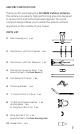
ASSEMBLY INSTRUCTIONS: Thank you for purchasing the GE 33685 Outdoor Antenna. This antenna is a sturdy, high-performing antenna designed to receive UHF and VHF broadcasted signals. The small, compact design allows you to install the antenna almost anywhere on the outside of your house. PARTS LIST: 1) Main Housing Unit 1 ea. 2) Main Boom 1 with Short Dipoles 1 ea. 3) Main Boom 2 with VHF Elements 1 ea. 4) Main Boom Connector Piece 1 ea. (pre-attached to the Main Boom 1) 5) UHF Elements (32.
PARTS LIST (CONT): 12) ¼ X 2” Lag Screws 4 ea. 13) M6 X 50mm Bolts 2 ea. 14) M6 Locking Nuts 2 ea. 15) M6 Washers 4 ea. 16) M5 X 40mm Bolt 1 ea. 17) M5 Nut 1 ea. 18) M4 Lock washers 2 ea. (pre-attached to the Main Housing Unit) 19) Small Zip Tie 1 ea. 20) Large Zip Tie 2 ea. 21) M3 X 16mm self-tapping screw 1 ea. 22) Danger Label 1 ea.
ASSEMBLING THE ANTENNA: 1) Connecting the UHF Dipoles a) Turn the Main Housing Unit with the bottom side facing up. (Fig. 1a) Fig. 1a b) Slide one of the UHF Elements into the Main Housing Unit from the left side. (Fig. 1a) c) Slide the other UHF Element into the Main Housing Unit from the right side into the first UHF Element. (Fig. 1b)Align the holes of the UHF elements with the embossed black markings in the center of the Main Housing Unit. Fig.
2) Main Boom Assembly: a) Take the Main Boom 1, turn it with the short dipoles facing up. b) Take the Main Boom 2, turn it with the VHF connector rods marked L and R facing up and slide the Main Boom 2 onto the Main Boom Connector Piece pre-attached to the Main Boom 1. (Fig. 2) Fig. 2 3) Assembling the Main Boom To The Main Housing Unit: a) Position the Main Housing Unit with the bottom side facing up. Remove the four #6 X 32 Wing Nuts and the two M4 Lock Washers.
ii. Slide the two VHF connector rods marked L and R over the two bolts on the Main Housing Unit, slide the M4 Lock Washers onto the bolts and secure with the #6 X 32 Wing Nuts. (Fig. 3b) Fig. 3b iii. Unfold the two VHF element rods and snap into the bracket. (Fig. 3c) Fig. 3c 4) Attach the Mast Clamp to the Main Boom: a) b) c) Remove the two #10 X 24 Wing Nuts from the ”U” Bolt and Clamp Assembly.
5) Installing the Assembled Antenna: a) Locate a position on the house that is far away from power lines. Refer to the Important Safety Instructions. b) Secure the Mounting Bracket to the location selected for the antenna. The 1/4 X 2” Lag Screws have been provided for some installations. c) Connect the “J” mount to the Mounting Bracket (Fig. 5a) using the M6 X 50mm Bolts, M6 Locking Nuts and M6 Washers. Fig.
Antenna Grounding & Connection The National Electric Code (NEC) requires your outdoor antenna installation to be properly grounded. This involves grounding both the antenna and the antenna mounting structure. This helps protect you and your property in the event of static build up on the antenna or lightning near your home. Note: If you previously had a satellite or cable system installed at your home, you may be able to use some of the parts from this system for your antenna installation.
Examples of acceptable building grounding locations are: • The building or structure grounding electrode system as covered in 250.50 in the NEC. • Grounded interior metal water piping system, within 5ft. from its point of entrance to the building. • Grounded nonflexible metallic power service raceway. • Service equipment enclosure, the grounding electrode conductor or the grounding electrode conductor metal enclosure of the power service.
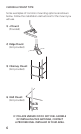
If you are using a pre-built cable that has connectors, follow these steps. i. Cut 4 slits spaced evenly apart at the narrow tip of the provided Rubber Boot approximately ¼” in length. (Fig. 6c) Fig. 6c ii. Run the coax cable through the narrow end of the Rubber Boot and attach the cable to the antenna. iii. Slide the Rubber Boot into the round channel on the Main Housing Unit. iv.
c) Ground the 75 OHM Grounding Block: Connect a #8 aluminum or #10 grounding wire to a screw terminal provided on the 75 ohm grounding block. Connect the other end of the wire to an acceptable building ground location. Refer to step a) in this section for acceptable building grounding locations. Be sure to double check all your connections after your installation is complete.
Easy Installation Guides EASY INSTALLATION FOR TODAY’S HDTVS 1) Connect the coax cable from the antenna to the antenna input on your HDTV. 2) Follow your HDTV’s instruction manual to scan for channels on your television. EASY INSTALLATION FOR ANALOG TVS WITH SET-TOP BOX 1) Connect the coax cable from the antenna to your set-top box antenna input. Then connect another coax cable (not included) to the antenna output on the set-top box.
ANTENNA HELPFUL TIPS Maximize the number of channels you receive by aiming the antenna in different directions to see which position provides the best reception and the maximum number of channels. Be sure to run a new channel scan for each position. Refer to the instruction manual that came with your TV if you are not sure how to do this. Visit www.antennaweb.org or www.dtv.