45231 Home Monitoring Wired Color Camera User Manual For indoor/outdoor use. Do not use in wet locations. www.jascoproducts.
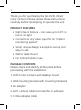
Thank you for purchasing the GE 45231 Wired Color Camera. Please review these instructions carefully before attempting to operate the unit. PRODUCT FEATURES • Night Vision feature – can view up to 10 ft. in low or no light • Connects to any video input for an “instant monitoring system” • Small, unique design is simple to set up and easy to use • Wall or desk mount • For Indoor/Outdoor use PACKAGE CONTENTS Please check and identify all the parts before proceeding with the installation. 1.
CHOOSING A CAMERA MOUNTING LOCATION The 45231 Color Camera can be positioned on a desktop, or mounted to a wall. It is suitable for indoor or outdoor use. When choosing a mounting location, please be advised: • Do not use in wet locations. If using outdoors, position in sheltered location. • DO NOT position the camera so that it points directly into the sun or any bright light, as this may cause damage to the camera.
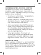
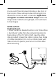
CONNECTING TO A TV The 45231 connects to the video and audio input jacks on the back of your TV, VCR or DVR. If you are not using a VCR or DVR, connect the 45231 Color Camera to your TV as shown below. TV Power Video In Audio In To view: 1. Switch on the TV; set the volume to midpoint. Connect to the 45231 Color Camera. Note: For temporary installation you can connect the camera to the TV, VCR or DVR without using the 60 ft. extension cable.
remote control. You should now be able to see and hear the output from the camera. Note: You can extend the cable using the 60 ft. extension cable at any time to optimally locate the camera (provided the cable length is sufficient). The camera cable can be extended up to 300 ft. Contact the Customer Service Group (1-800-654-8483) to purchase extension cables.
and the white cable to the left/mono audio jack. You can extend the cable using the extension cable at any time to optimally locate the camera (provided the cable length is sufficient). 2. Select the VCR channel on your TV (3 or 4). This should be the normal channel or input you normally use to watch the VCR or DVR. 3. Select the AV input on your VCR or DVR by pressing the button labeled AV or VIDEO on the VCR/DVR or on the VCR/DVR’s remote control.
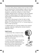
It turns on/off the Infra-Red (IR) LEDs on the front of the camera. These LEDs provide artificial light that allows the camera to ‘see’ in the dark. Night Vision will appear as a Black and White image. When the image sensor detects enough light, color will return to the images. INSTALLATION Desktop Mount: 1. Place camera in desired location on a flat surface. 2. Run the 60’ cable from the camera’s location to the location of the TV, VCR or DVR. Use the cable clips provided to keep the cable in place.
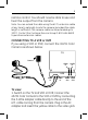
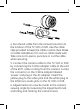
3. Connect the camera cable to the TV, VCR or DVR by connecting the 3-Wire adapter cable to the end of the 60 ft. cable coming from the camera. (See diagram). Locate the connector on the 3-Wire adapter labeled ‘power’ and plug in the AC adapter. Insert the yellow plug to the video jack and the white plug to the left/mono audio jack on the TV, VCR or DVR. 4. Switch on the power to the TV, VCR or DVR. Select appropriate AV input on TV, VCR or DVR.
4. Run the 60’ cable from the camera’s location to the location of the TV, VCR or DVR. Use the cable clips provided to keep the cable in place. (See Notes on Cable Installation.) Do not run cable inside wall; Take care not to pierce, puncture or cut the cable when securing. 5. Connect the camera cable to the TV, VCR or DVR by connecting the 3-Wire adapter cable to the end of the 60 ft. cable coming from the camera. Locate the connector on the 3-Wire adapter labeled ‘power’ and plug in the AC adapter.
NOTES ON CABLE INSTALLATION 1. Use care when running the cable from the camera to the TV, VCR or DVR; when securing the cable, do not cut, pierce or puncture. DO NOT RUN CABLE INSIDE WALLS. 2. Keep the camera cable away from other cables where possible, in order to reduce the risk of picture and audio interference. 3. Avoid laying the cable next to any heat sources. 4.
Output current ............................................................................................ 400mA Camera Camera operating voltage......................................................................9V DC Current consumption .......................................................100mA maximum Camera type.............................................................................Color 1/4” CMOS Horizontal resolution .....................................................................
WARNING Risk of fire and shock • Only use the supplied cUL listed AC to DC adapter. • The supplied adapter is for indoor use only. • Do not run the camera cable inside walls; when securing the cable, do not cut or puncture • Do not use in wet locations FCC STATEMENT NOTE: This equipment has been tested and found to comply with the limits for a Class B digital device, pursuant to Part 15 of the FCC Rules.