
Instruction Manual


10. Connect the black wire that comes from the electrical
service panel (Hot) to the lead or terminal marked LINE.
11. Connect the Traveler wire (usually Red) to the wire or
screw terminal marked TRAVELER. The other end of
this Traveler wire connects to the TRAVELER wire on
the 45610 Auxiliary Switch. The TRAVELER terminal
or lead must be insulated if you are not using it.
See the following section for information about wiring
the 45610 Auxiliary Switch.
12. Insert Z-Wave Switch into the switch box being careful
not to pinch or crush wires.
13. Secure the switch to the box using the supplied screws.
14. Mount the wall plate.
15. Reapply power to the circuit at fuse box or circuit
breaker and test the system.
Note: UL species that the tightening torque for the screw
terminals is 14Kgf-cm.
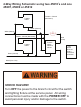
45610 for 3 or 4-Way Control:
1. The 45610 requires the following 3 wiring connections:
a. The Traveler wire. This is used to send voltage signals to
the primary Z-Wave switch. The signals tell the Z-Wave
switch what action to perform.
b. Ground.
c. Neutral.
2. DO NOT connect the 45610 auxiliary switch to the
home’s black Hot (Line) wire.