Room Air Conditioners www.GEAppliances.com Cool Only: AJCH AJCH AJCQ AJCQ AJCS AJCS AJCS 08, 10 10, 12 08, 10 10, 12 06 08, 10 09, 10, 12 ACB DCB ACB DCB LCB ACB DCB Heat/Cool: AJEH AJES AJES AJES AJES 12 06 08 09, 10, 12 10 DCB LSB ASB DCB DSB Heat Pump: AJHS 08 AJHS 08, 10 Write the model and serial numbers here: Model # __________________________ Serial # ____________________________ Find these numbers on a label on the front of the base pan behind the front grille.
WARNING! For your safety, the information in this manual must be followed to minimize the risk of fire, electric shock or personal injury. SAFETY PRECAUTIONS Operating Instructions Safety Instructions IMPORTANT SAFETY INFORMATION. READ ALL INSTRUCTIONS BEFORE USING. Installation Instructions Care and Cleaning ■ Use this appliance only for its intended purpose as described in this Owner’s Manual. ■ Turn the mode control OFF and unplug your air conditioner before making any repairs or cleaning.
WARNING! USE OF EXTENSION CORDS—115-Volt models only However, if you must use an extension cord, it is absolutely necessary that it be a UL-listed, 14 gauge, 3-wire grounding type appliance extension cord having a grounding type plug and outlet and that the electrical rating of the cord be 15 amperes (minimum) and 125 volts. CAUTION: Operating Instructions Because of potential safety hazards under certain conditions, we strongly recommend against the use of an extension cord.
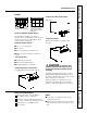
COOL MODE Remote Control become cooler. Set the thermostat at a higher number and the indoor air will become warmer. 1. Press COOL pad. 2. Press LOW, MED or HI pads to set desired fan speed. Control Panel 1. Press the MODE pad until the COOL indicator light is lit and the LOW, MED or HI indicator light is lit for the desired fan speed. 2. Press the INCREASE ▲ / DECREASE ▼ pads to set the desired temperature 60°F to 85°F in 1°F increments.
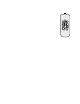
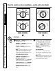
Operating Instructions HIGH HEAT C ER LOW COOL ER OL LOW HEAT HIGH FAN RM OFF WA LOW FAN O Safety Instructions About the controls on the air conditioner—models with control knobs. HIGH COOL OFF Care and Cleaning ER HIGH COOL MODE CONTROL Installation Instructions OL HIGH FAN LOW COOL CO LOW FAN TEMP CONTROL Controls Mode Control Temp Control HIGH COOL and LOW COOL provide cooling with different fan speeds. The temp control is used to maintain the room temperature.
Fan Switch Operating Instructions On Heat/Cool models, the fan switch lever is located in a hole through the control panel. To reach it, you need to remove the front grille. Use a small screwdriver to change the setting. Cool only models have a rocker switch on the front of the control box. Safety Instructions www.GEAppliances.com When set at CYCLE (down) the fan cycles on and off when cooling or heating.
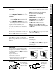
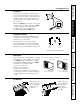
Safety Instructions Operating Instructions Care and Cleaning Front Grille The front grille can be removed for more thorough cleaning or to make the model and serial numbers accessible. 3. Pull the grille out from the bottom and lift up from the tabs on the top of the case. To remove: Troubleshooting Tips Installation Instructions 1. Pull the filter out. 2. Remove the two grille screws. To replace: Hook the tabs on the front grille even with the tabs on the case and snap into place.
To maintain optimum performance, clean the filter at least every 30 days. Air Filter FRONT FRONT To remove the air filter, on other models: Safety Instructions www.GEAppliances.com Pull it down. Operating Instructions Dirty filter—Needs cleaning Clogged filter—Greatly reduces cooling, heating and airflow. Turn the air conditioner off before cleaning. Keeping the air filter clean will: To replace the air filter: Replace the clean filter by pushing it back into place.
Installation Instructions Air Conditioner Questions? Call 800.GE.CARES (800.432.2737) or Visit our Website at: www.GEAppliances.com BEFORE YOU BEGIN CAUTION: Do not, under any circumstances, cut or remove the third (ground) prong from the power cord. Do not change the plug on the power cord of this air conditioner. Aluminum house wiring may present special problems—consult a qualified electrician. Read these instructions completely and carefully.
Installation Instructions Read these instructions completely and carefully.
Installation Instructions INSTALLING A J-MODEL IN AN EXISTING WALL CASE Read these instructions completely and carefully. 1 REMOVE LOCKING PLATE ON 4 REINSTALL LOCKING PLATE WITH FRONT LEFT SIDE TAB BEHIND WALL CASE FLANGE.
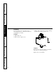
Installation Instructions INSTALLING THROUGH THE WALL Read these instructions completely and carefully. 1 PREPARE OPENING IN WALL 3 SUPPORT REQUIREMENTS FOR AIR CONDITIONER Make certain a wall receptacle is available close to the hole location or make arrangements to install a receptacle. The cord length for the 115-volt models is 72″ to the right and 47″ to the left. For the 230/208-volt models the cord length is 65″ to the right and 39″ to the left.
Installation Instructions WINDOW INSTALLATION—OPTIONAL FOR MODELS AJES06LSB, AJES08ASB, AJES10DSB and AJHS08ASB Read these instructions completely and carefully.
Installation Instructions 2 STORM WINDOW REQUIREMENTS A storm window frame will not allow the air conditioner to tilt towards the outside and will keep it from draining properly. To adjust for this, attach a piece of wood to the stool. Wood 1/2″ higher than frame Sill Stool Storm window frame WOOD PIECES: WIDTH: 2″ LENGTH: Long enough to fit inside the window frame. THICKNESS: To determine the thickness, place a piece of wood on the stool to make it 1/2″ higher than the top of the storm window frame.
Installation Instructions WINDOW INSTALLATION—OPTIONAL (cont.) 4 PREPARE WINDOW B Measure 123⁄8″ from the centerline on both sides for the sill support brackets. A Mark the centerline of the stool. Measure from the centerline 133⁄8″ on both sides for the panel cuts. Centerline Centerline Stool 133⁄8″ 123⁄8″ Sill 5 INSTALL SILL SUPPORTS C Turn the bolts and tighten the lock nuts to make the sill supports level or tilt down 1/8″ to the outside. Line up the “V” notch with 123⁄8″ marks.
Installation Instructions 6 MEASURE, CUT AND INSTALL Angle Gasket FILLER PANELS A Measure from the edge of the panel marks (see Prepare the Window) to the inside of the window track on each side. (A and B) Angle Sill Window track 133⁄8″ A Gasket 133⁄8″ Right side D Install the panels in the window. Place the spring clips 3″ from the top and the bottom. Squeeze and push the clips to fit in the window track and the tab into the sill support.
Installation Instructions WINDOW INSTALLATION—OPTIONAL (cont.) 7 INSTALL CASE IN WINDOW E With the window closed, mark where the window sash meets the case. A Peel off the backing from the bottom window gasket. F B Place the gasket on the stool and over the brackets, even with the rear edge, sticky side down. Peel off the backing from the case top gasket. G Hold on to the case, open the window, and place the gasket along the mark on the case.
Installation Instructions 8 INSTALL WINDOW GASKET AND LOCKING BRACKET C Attach the window locking bracket with 1 type E screw. A Cut the foam top window gasket to the window width. B Stuff the foam between the glass and the window to prevent air and insects from getting into the room. 9 REPLACE AIR CONDITIONER IN C When the wall outlet is to the left, extend the cord under the unit and hold it in place with the clamp. CASE A Carefully slide the air conditioner back into the case.
Safety Instructions Troubleshooting Tips: Save time and money! Review the chart below first and you may not need to call for service. Problem Possible Causes What To Do Air conditioner does not start The air conditioner is unplugged. • Make sure the air conditioner plug is pushed completely into the outlet. The fuse is blown/circuit breaker is tripped. • Check the house fuse/circuit breaker box and replace the fuse or reset the breaker. Power failure.
All warranty service provided by our Factory Service Centers, or an authorized Customer Care® technician. To schedule service, on-line, 24 hours a day, visit us at www.GEAppliances.com, or call 800.GE.CARES (800.432.2737). For service in Canada, call 1.800.361.3400. Staple your receipt here. Proof of the original purchase date is needed to obtain service under the warranty.
Instructions de sécurité . . . . . . . 23, 24 Instructions de fonctionnement Réglages—Boutons de réglage . . 27, 28 Réglages—Touches à effleurement . . . . . . . . . . . . . . . . .25, 26 Entretien et nettoyage Filtre à air . . . . . . . . . . . . . . . . . . . . . 30 Grille frontale . . . . . . . . . . . . . . . . . . .29 Grille et boîtier . . . . . . . . . . . . . . . . . 29 Serpentins extérieurs . . . . . . . . . . . . 29 Instructions de montage Avant de commencer . . . . . . . . . .
AVERTISSEMENT! Pour votre sécurité, vous devez suivre les instructions de ce manuel pour réduire les risques d’incendie, de secousse électrique et de blessure. ■ N’utilisez cet appareil que pour son usage prévu, tel que décrit dans le Manuel de l’utilisateur. ■ Vous devez bien monter ce conditionneur, conformément aux Instructions de montage, avant de l’utiliser. ■ Réparez ou remplacez tout cordon d’alimentation effiloché ou autrement endommagé.
AVERTISSEMENT! UTILISATION DE RALLONGES—modèles de 115 volts uniquement À cause du danger qu’elles font courir dans certaines conditions, nous vous recommandons instamment de ne pas utiliser de rallonge. Instructions de fonctionnement Instructions de sécurité RENSEIGNEMENTS IMPORTANTS EN MATIÈRE DE SÉCURITÉ. LISEZ TOUTES LES INSTRUCTIONS AVANT USAGE.
www.electromenagersge.ca L’aspect peut varier. Climatisation Ventilateur Minuterie en position Arrêt Moyen Bas Sommeil Marche Commandes du conditionneur ON/STOP (MARCHE/ARRÊT) Met le conditionneur en position de marche ou d’arrêt. Display (Affichage) Sur la télécommande, utilisez cette fonction pour régler le conditionneur au mode COOL ou FAN. Sur les commandes du conditionneur, utilisez cette fonction pour régler le mode COOL ou FAN à la vitesse de ventilateur HIGH, MED ou LOW.
MODE CLIMATISATION (COOL) Télécommande 1. Appuyez sur la touche COOL. 2. Appuyez sur les touches LOW, MED ou HI pour régler la vitesse de ventilateur voulue. 3. Appuyez sur les touches INCREASE ▲ / DECREASE ▼ pour régler la température voulue entre 60°F (16°C) et 85°F (30°C) par incréments de 1°F (0,5°C). Tableau de commande 1.
Commandes Commande du mode Les fonctions HIGH COOL et LOW COOL génèrent du refroidissement à différentes vitesses de ventilateur. Les fonctions HIGH HEAT et LOW HEAT génèrent du chauffage à différentes vitesses de ventilateur. Les fonctions LOW FAN et HIGH FAN génèrent le filtrage et la circulation d’air sans refroidissement ou chauffage, à différentes vitesses de ventilateur.
Interrupteur du ventilateur Sur les modèles avec chauffage/climatisation, le levier de l’interrupteur du ventilateur est situé dans un trou sur le tableau de commande. Pour l’atteindre, vous devez retirer la grille frontale. Utilisez un petit tournevis pour changer le réglage. Les modèles avec climatisation seulement dont dotés d’un interrupteur à bascule sur le devant de la boîte de commande.
Entretien et nettoyage du conditionneur. www.electromenagersge.ca Grille et boîtier Éteignez le conditionneur et retirez la fiche d’alimentation électrique de la prise murale avant le nettoyage. Pour nettoyer, utilisez de l’eau et un détergent doux. N’utilisez jamais d’agent de blanchiment ou d’abrasif. Serpentins extérieurs Les serpentins situés du côté extérieur du conditionneur doivent être vérifiés régulièrement.
Pour conserver un rendement optimal, nettoyez le filtre au moins tous les 30 jours. Filtre à air Pour retirer le filtre à air, sur certaines modèles : Tirer vers le bas. Instructions de fonctionnement Instructions de sécurité Entretien et nettoyage du conditionneur. Éteignez le conditionneur avant le nettoyage. Entretien et nettoyage La mesure la plus utile que vous pouvez prendre pour entretenir votre conditionneur est de nettoyer le filtre au moins tous les 30 jours.
Conditionneur d’air Instructions de montage Questions? Composez le 1.800.361.3400 ou visitez notre site web à : www.electromenagersge.ca AVANT DE COMMENCER ATTENTION : N’enlevez, ne coupez ou n’ôtez jamais la troisième broche (de mise à la terre) du cordon d’alimentation. Ne changez jamais la fiche du cordon d’alimentation de ce conditionneur. Un câblage de la maison en aluminium peut occasionner des problèmes particuliers—consultez un électricien qualifié.
Instructions de montage Veuillez lire toutes ces instructions attentivement.
Instructions de montage INSTALLATION D’UN MODÈLE « J » DANS UN LOGEMENT MURAL EXISTANT Veuillez lire toutes ces instructions attentivement.
Instructions de montage INSTALLATION À TRAVERS LE MUR Veuillez lire toutes ces instructions attentivement. 1 PRÉPARATION DE L’OUVERTURE 3 SUPPORT DU CONDITIONNEUR DANS LE MUR Le mortier entre le logement et la brique autour du logement peut être creusé à 45° pour améliorer le calfeutrage. Assurez-vous qu’une prise murale se trouve à proximité de l’ouverture ou installez-en une. La longueur du cordon des modèles 115 volts est 72 po (1,8 m) à droite et 47 po (1,2 m) à gauche.
Instructions de montage INSTALLATION DE FENÊTRE (EN OPTION) POUR LES MODÈLES AJES06LSB, AJES08ASB, AJES10DSB et AJHS08ASB Lisez toutes ces instructions attentivement.
Instructions de montage INSTALLATION DE FENÊTRE (EN OPTION) (suite) 2 INSTRUCTIONS RELATIVES À LA CONTRE-FENÊTRE Le cadre de la contre-fenêtre empêche le conditionneur de pencher vers l’extérieur et donc de se drainer adéquatement. Pour régler ce problème, fixez une pièce de bois sur le rebord de fenêtre. 1/2 po plus élevé que le cadre Cadre de la contrefenêtre Bois Seuil Rebord PIÈCES DE BOIS : LARGEUR : 2 po LONGUEUR : Suffisamment longue pour se loger à l’intérieur du cadre de fenêtre.
Instructions de montage 4 PRÉPAREZ LA FENÊTRE B Mesurez 123⁄8 po de chaque côté de la ligne de centre pour déterminer la position des ferrures de support de seuil. A Tracez la ligne de centre du rebord de fenêtre. Mesurez 133⁄8 po de chaque côté de la ligne de centre pour tracer la position des panneaux.
Instructions de montage INSTALLATION DE FENÊTRE (EN OPTION) (suite) Joint d’étanchéité 6 MESUREZ, COUPEZ ET INSTALLEZ Angle LES PANNEAUX DE FERMETURE A De chaque côté (A et B), mesurez la distance entre la marque du panneau (voir Préparez la fenêtre) et l’intérieur du rail de la fenêtre. Seuil Rail de la fenêtre 133⁄8 po A Type C (vis peintes) Joint d’étanchéité 133⁄8 po Côté droit D Montez les panneaux dans la fenêtre. Placez les brides à ressort à 3 po du haut et du bas des panneaux.
Instructions de montage 7 MONTEZ LE LOGEMENT DANS LA E La fenêtre étant fermée, marquez l’endroit où le châssis de la fenêtre entre en contact avec le logement du conditionneur. FENÊTRE A Enlevez le doublage en papier du joint d’étanchéité inférieur de la fenêtre. B Placez le joint d’étanchéité sur le rebord de la fenêtre et par-dessus les supports, à égalité avec le bord arrière, surface adhésive vers le bas. F Enlevez le doublage en papier du joint d’étanchéité de la paroi supérieure du logement.
Instructions de montage INSTALLATION DE FENÊTRE (EN OPTION) (suite) 8 MONTEZ LE JOINT D’ÉTANCHÉITÉ EN MOUSSE DE LA FENÊTRE ET LA FERRURE DE VERROUILLAGE C Fixez la ferrure de verrouillage de la fenêtre à l’aide d’une (1) vis de type E. A Coupez, à la largeur de la fenêtre, le joint d’étanchéité supérieur en mousse. B Insérez la mousse entre la vitre et la fenêtre pour empêcher l’air et les insectes de pénétrer dans la pièce.
Instructions de sécurité Notes.
Instructions de sécurité En cas de panne : Économisez du temps et de l’argent! Étudiez le tableau ci-dessous : votre appel de service est peut-être inutile. Problème Causes possibles Que faire Le conditionneur ne se met pas en marche Le conditionneur est débranché. • Assurez-vous que la fiche du conditionneur soit bien branchée dans la prise murale. Le fusible a sauté/ le disjoncteur est ouvert. • Vérifiez la boîte à fusible/à disjoncteurs et remplacez le fusible ou rebranchez le disjoncteur.
Tout le service en vertu de la garantie est offert par nos centres de service d’usine ou par un technicien autorisé de Customer Care®. Pour obtenir le service, appelez le 1.800.361.3400. Agrafez le reçu d’achat ici. Pour obtenir le service sous garantie, vous devrez fournir la preuve de l’achat original. Un an À partir de la date d’achat original Toute pièce du conditionneur qui ne fonctionne pas à cause d’un vice de matériau ou de main-d’œuvre.
Soutien au consommateur. Site Web appareils électroménagers GE www.electromenagersge.ca Vous avez une question ou vous avez besoin d’aide pour votre appareil électroménager? Contactez-nous par Internet au site www.electromenagersge.ca 24 heures par jour, tous les jours de l’année. Service de réparations 1.800.361.3400 Le service de réparations GE est tout près de chez vous. Pour faire réparer votre électroménager GE, il suffit de nous téléphoner.
Instrucciones de seguridad . . . 46, 47 Instrucciones de operación Controles—botones de control . . . . . . . . . . . . . . . . . . 50, 51 Controles—teclas de toque . . . .48, 49 Cuidado y limpieza Filtro de aire . . . . . . . . . . . . . . . . . . . 53 Rejilla delantera . . . . . . . . . . . . . . . . .52 Rejilla y caja . . . . . . . . . . . . . . . . . . . . 52 Bobinas para exteriores . . . . . . . . . . 52 Instrucciones de instalación Antes de empezar . . . . . . . . . . . . .
Seguridad INFORMACIÓN IMPORTANTE DE SEGURIDAD. LEA TODAS LAS INSTRUCCIONES ANTES DE USAR. ¡ADVERTENCIA! Por su seguridad, se debe seguir la información en este manual para minimizar el riesgo de incendios, descargas eléctricas o lesiones personales. PRECAUCIONES DE SEGURIDAD Operación ■ Use este electrodoméstico solamente para el propósito determinado según se describe en el Manual del propietario.
¡ADVERTENCIA! USO DE CABLES DE EXTENSIÓN—Modelos de 115 voltios solamente PRECAUCIÓN: NO USE un cable de extensión con ninguno de los modelos de 230/208 voltios Operación Debido al potencial de riesgos de seguridad bajo ciertas condiciones, enérgicamente recomendamos contra el uso de cables de extensión.
Apoyo al consumidor Solucionar problemas 48 Instalación Cuidado y limpieza Operación Seguridad
MODO COOL (FRIO) Interruptor del ventilador El interruptor del ventilador está localizado detrás de la rejilla delantera en la caja de control. Cuando se fija en CYCLE (abajo) el ventilador inicia el ciclo de encendido y apagado. Cuando se fija en CONT (continuo, arriba) el ventilador opera todo el tiempo ofreciendo una temperatura más balanceada. La unidad se envía de fábrica con la posición CONT. Cuidado y limpieza deseada. Ajuste el termostato a un número menor y el aire interno se enfriará más.
OFF Operación HIGH COOL OFF ER Cuidado y limpieza OL HIGH FAN LOW COOL CO LOW FAN HIGH COOL CONTROL DE MODO CONTROL DE LA TEMPERATURA Instalación Controles Control de Modo Los niveles HIGH COOL y LOW COOL enfrían con diferentes velocidades del ventilador. HIGH HEAT y LOW HEAT calientan con diferentes velocidades del ventilador.
Interruptor del ventilador Operación En modelos de Calefacción/ Enfriamiento, la palanca del interruptor del ventilador se encuentra ubicada en un orificio a través del panel de control. Es necesario retirar la rejilla delantera para alcanzarlo. Use un destornillador pequeño para cambiar el nivel. Los modelos para enfriamiento únicamente tienen un interruptor de balancín al frente de la caja de control.
Seguridad Cuidado y limpieza del acondicionador de aire. Rejilla y caja Apague el acondicionador de aire y retire el enchufe de la toma corriente antes de limpiar. Para limpiar, use agua y un detergente suave. No use blanqueador o abrasivos. Bobinas exteriores Cuidado y limpieza Operación Los resortes en el lado exterior del acondicionador de aire deben revisarse con frecuencia.
Para mantener un desempeño óptimo, limpie el filtro al menos cada 30 días. Filtro de aire FRONT Para retirar el filtro de aire, en otros modelos: Seguridad www.GEAppliances.com Hálelo hacia abajo. Operación Filtro sucio – necesita limpieza Filtro obstruido – reduce en gran parte el enfriamiento, la calefacción y el flujo del aire. Apague el acondicionador de aire antes de limpiar. Para reemplazar el filtro del aire Reemplace el filtro limpio empujándolo de nuevo en su lugar.
Instrucciones Acondicionadores de Aire de instalación ¿Preguntas? Llame al 800.GE.CARES (800.432.2737) o bien visite nuestra página Web: GEAppliances.com ANTES DE INICIAR PRECAUCIÓN: Bajo ninguna circunstancia corte o remueva la tercera púa (conexión a tierra) del cable eléctrico. No cambie el enchufe en el cable eléctrico de este acondicionador de aire. Los cables caseros de aluminio podrían presentar problemas especiales. Consulte a un técnico electricista calificado.
Instrucciones para la instalación Lea estas instrucciones completa y cuidadosamente.
Instrucciones para la instalación CÓMO INSTALAR UN MODELO J EN UNA CAJA DE PARED EXISTENTE Lea estas instrucciones completa y cuidadosamente. 1 RETIRE LA PLACA DE BLOQUEO EN 4 VUELVA A INSTALAR LA PLACA EL LADO IZQUIERDO DELANTERO DE BLOQUEO CON LA PESTAÑA DETRÁS DEL REBORDE DE LA CAJA DE PARED.
Instrucciones para la instalación CÓMO INSTALAR A TRAVÉS DE LA PARED Lea estas instrucciones completa y cuidadosamente. 1 PREPARE LA ABERTURA DE LA 3 REQUISITOS DE APOYO PARA EL PARED ACONDICIONADOR DE AIRE Verifique que haya un receptáculo de pared disponible cercano a la ubicación del orificio o disponga la instalación de un receptáculo. La longitud del cable para los modelos de 115 voltios es 72″ hacia la derecha y 47″ hacia la izquierda.
Instrucciones para la instalación INSTALACIÓN DE VENTANA—OPCIONAL PARA MODELOS AJES06LSB, AJES08ASB, AJES10DSB y AJHS08ASB Lea estas instrucciones completa y cuidadosamente.
Instrucciones para la instalación 2 REQUISITOS DE VENTANA PARA TORMENTA Un marco de ventana para tormenta no permitirá que el acondicionador de aire se incline hacia fuera e impedirá que se drene correctamente. Para ajustarla, agregue un pedazo de madera a la alfajía exterior. 1/2″ más alto que el marco Marco de ventana para tormenta Madera Alfajíaior exter Alfajía interior PIEZAS DE MADERA: ESPESOR: 2″ LONGITUD: Suficiente longitud para ajustarse al interior del marco de la ventana.
Instrucciones para la instalación INSTALACIÓN EN UNA VENTANA—OPCIONAL (cont.) 4 PREPARE LA VENTANA B Mida 123⁄8″ desde la línea central en ambos lados para los soportes de apoyo de la alfajía exterior. A Marque la línea central de la alfajía interior. Mida desde la línea central 133⁄8″ en ambos lados para los cortes de los paneles.
Instrucciones para la instalación 6 MIDA, CORTE E INSTALE LOS PANELES DE RELLENO A Mida desde el borde de las marcas de los paneles (ver Prepare la ventana) hacia el interior del riel de la ventana en cada lado. (A y B) B Marque las medidas A y B en cada lado de la placa del panel de relleno. Corte los paneles y deseche la pieza del centro. Observe la posición de las muescas. C Una las armazones de los paneles. Retire el protector de papel del empaque lateral de la caja y péguelo al ángulo.
Instrucciones para la instalación INSTALACIÓN EN UNA VENTANA—OPCIONAL (cont.) 7 INSTALE LA CAJA EN LA E Con la ventana cerrada, marque dónde el marco de la ventana se encuentra con la caja. VENTANA A Pele la protección del empaque para la parte inferior de la ventana. F B Coloque el empaque en la alfajía interior sobre los soportes, al mismo nivel del borde posterior, con el lado pegajoso hacia abajo. G Sostenga la caja, abra la ventana y coloque el empaque a lo largo de la marca de la caja.
Instrucciones para la instalación 8 INSTALE EL EMPAQUE PARA LA VENTANA Y EL SOPORTE DE BLOQUEO C Una el soporte de bloqueo de la ventana con un tornillo tipo E. A Corte el empaque de espuma para la parte superior de la ventana al ancho de la ventana. B Rellene la espuma entre el vidrio y la ventana para evitar que el aire y los insectos entren en la habitación.
Seguridad Ideas para la identificación y solución de problemas: ¡Ahorre dinero y tiempo! Revise la siguiente tabla primero y quizás no tenga que llamar para solicitar servicio. Problema Causas posibles Qué hacer El acondicionador de aire no enciende El acondicionador de aire está desconectado. • Cerciórese de que el acondicionador de aire está enchufado totalmente en el tomacorriente.
Operación Cuidado y limpieza Instalación Solucionar problemas Apoyo al consumidor 65 Seguridad www.GEAppliances.com Notas.
Seguridad Operación Cuidado y limpieza Instalación Apoyo al consumidor Solucionar problemas Garantía de su acondicionador de aire. Grape aquí su recibo. Se requiere facilitar prueba de la fecha de compra original para obtener un servicio bajo la garantía. Por el período de: Nosotros reemplazaremos: Un año A partir de la fecha de la compra original Cualquier parte del acondicionador de aire que falle debido a defectos en los materiales o en la fabricación.
Apoyo al Consumidor. Página Web de GE Appliances www.GEAppliances.com ¿Tiene alguna pregunta sobre su electrodoméstico? ¡Pruebe la página Web de GE Appliances 24 horas al día, cualquier día del año! Para mayor conveniencia y servicio más rápido, ya puede descargar los Manuales de los Propietarios, pedir piezas o incluso hacer una cita en línea para que vengan a realizar una reparación. También puede “Ask Our Team of Experts™” (Preguntar a nuestro equipo de expertos) sobre cualquier cuestión y mucho más...
Consumer Support. GE Appliances Website www.GEAppliances.com Have a question or need assistance with your appliance? Try the GE Appliances Website 24 hours a day, any day of the year! For greater convenience and faster service, you can now download Owner’s Manuals, order parts, catalogs, or even schedule service on-line. You can also “Ask Our Team of Experts™” your questions, and so much more... Schedule Service www.GEAppliances.com Expert GE repair service is only one step away from your door.