
Installation Guide

READ THOROUGHLY BEFORE INSTALLING
WARNING
Risk of electric shock
• Turn power o before servicing
– see instructions
GEH-5983
INSTRUCTIONS
UltraStar
®
Luminaire
T5 / T8 Fluorescent Luminaire
GENERAL
This luminaire is designed for indoor applications only and should be installed and maintained
according to the following recommendations. Check label for damp or wet location suitability.
Any part damaged or broken during or after assembly or installation should be replaced.
UNPACKING
This Luminaire has been properly packed so that no parts should havebeen damaged
during transit. Inspect to conrm. No damaged parts should be installed.
Attention: Sheet metal parts may have sharp edges that may cause injury. The
manufacturer recommends caution during installation and the use of gloves when
possible. Remove all protective lm from reectors before energizing xture.
WIRING
Make all electrical connections in accordance with the National Electrical Code and any
applicable local code requirements. Check to be sure that labeled ballast voltage matches
supply voltage. Use supply wire rated minimum 90°C.
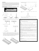
FIXTURE INSTALLATION (VH, HB, AL, SS, ES, FH, SR, NH, VP and EH Series)
a. EZ Leveling stright-cable or EZ Leveling Y-toggle cable can be used to mount
xture.
b. Attach EZ leveling cable to each end of xture, attaching through mounting slot.
2. S-Hook Hanging
Fixtures can be installed using S-hook (not supplied) using mounting detail on top
ends of xture.
3. NH series xture has integral threaded inserts and supplied eye-bolts.
Attach EZ level cable to eye-bolts for mounting of xture.
4. VP series xtures are supplied with mounting brackets. Attach EZ level cable to
mounting brackets for mounting of xture.
5. After xture is mounted access ballast for wiring as follows:
a. SR, ES, SS, AL Series: Remove reector/ballast cover by twisting reector
fasteners quarter-turn,
b. HB, NH Series: Remove top-access ballast cover by unsnapping ballast cover.
c. FH, VH Series: Plug directly into Modular Wiring Plug at side of ballast channel.
d. VP Series: Remove reector clips.
6. Make connection to ballast leads per wiring diagram on ballast.
7. Reinstall reector/ballast cover.
8. Peel protective covering from reector (Miro nish reectors).
9. Install lamps
LAMP
WARNING
Unit will fall if not installed properly
• Follow installation instructions
WARNING
Sharp edges may be present
• Gloves should be worn during installation
Installing SR, ES, SS, AL series xtures
1. EZ Leveling cable (see EZ Leveling cable attachment instructions below).
a. Four EZ Leveling straight- cables required to hang xture.
b. Attach EZ Leveling cable to each end of xture at mounting detail.
2. After xture is mounted:
a. Remove reector by turning reector fasteners quarter-turn.
b.
Make connection to ballast leads per wiring diagram on ballast.
c. Reinstall reector.
d. Peel protective covering from reector.
e. Install lamps.
Installing VH, HB, FH, NH, VP series xtures
1. EZ Leveling cable (see EZ Leveling cable attachment instructions below).
CAUTION
Risk of burn
• Allow lamp/xture to cool before handling
Use only lamps specied on nameplate. Observe lamp manufacturer’s recommendations
and restrictions on lamp operation, particularly ballast type, burning position, etc.
Attaching Modular Wiring Harness (optional component)
Insert supplied modular plug wiring harness into the receptacle on the end of the xture
and tie the wire to the cable hanger up to main power source.
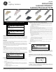
VH Series HB Series AL Series SS Series ES Series
FH Series SR Series NH Series EH Series VP Series
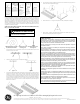
Components for Installing SS Series Fixtures
Reector/ballast cover must be installed to complete enclosure! Assemble reector part
RSFSS8-844UP-W only with BP-S082/ S081 Strip xture!
BR-S4-2LE-P-SS
Install socket/
socket bracket
assembly into
slots at end of
xture. Twist end
of tab with pliers
to insure locking
as shown.
BP-S054
If xture is run
across red iron,
use Bracket
Connector Kit for
alignment and
stiening.
BP-S009 or
BP-S067
If xture is run
with red iron,
use either a
slide-in connector
for alignment
proposes.
BP-S068
If xture is at the
end of a row, use
Tall End Plate
to cover end of
xture.
HW-F041
Attach alignment
clips to join
next reector if
required.
g
GE
Lighting Solutions
These instructions do not purport to cover all details or variations in equipment nor to provide for every possible contingency to be met in connection with installation, operation or
maintenance. Should further information be desired or should particular problems arise which are not covered suciently for the purchaser’s purposes, the matter should be referred to
GE Lighting Solutions.