
Specification Sheet

P-10/2008
GE Lighting Solutions • 1-888-MY-GE-LED • www.gelightingsolutions.com
1 - 8 8 8 - 6 9 - 4 3 - 5 3 3
Aluminum SQuARE STRAiGHT AREA
liGHTinG POlES
10 TO 30 fEET (3 TO 9 mETERS)
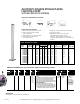
POLE SELECTION TABLE
Nominal Wall Bolt Approximate
Ordering Mounting Size Thickness Circle Bolt A. B. Base Plate Ship
Number Height (ft) (in.) (in.) 80 90 100 (in.) Size (in.) Projection (in.) Size (in.) Weight (lbs)
ASSA10XX4ADB 10 4 0.125 10.5 8.2 6.4 8-10 3/4x17 2.50 10.75 36
12XX4ADB 12 4 0.125 8.2 6.2 4.8 8-10 3/4x17 2.50 10.75 41
14XX4ADB 14 4 0.125 6.3 4.7 3.3 8-10 3/4x17 2.50 10.75 46
15XX4BDB 15 4 0.188 9.3 7.1 6.2 8-10 3/4X17 2.50 10.75 67
18XX4BDB 18 4 0.188 5.8 4.2 2.9 8-10 3/4X17 2.50 10.75 78
18XX4DDB 18 4 0.250 8.6 5.8 4.1 8-10 3/4X17 2.50 10.75 96
20XX4BDB 20 4 0.188 4.8 3.1 – 8-10 3/4X17 2.50 10.75 85
20XX4DDB 20 4 0.250 6.9 4.8 3.3 8-10 3/4X17 2.50 10.75 105
20XX5BDB 20 5 0.188 8.4 6.0 4.2 10-12 1X36 2.50 12 105
20XX5DDB 20 5 0.250 12.8 9.1 6.8 10-12 1X36 2.50 12 132
25XX5BDB 25 5 0.188 4.7 2.7 – 10-12 1X36 2.50 12 124
25XX5DDB 25 5 0.250 7.8 5.2 3.3 10-12 1X36 2.50 12 160
25XX6DDB 25 6 0.250 13.1 9.3 6.4 12-14 1X36 2.50 13.25 199
30XX6DDB 30 6 0.250 7.8 4.2 2.4 12-14 1X36 2.50 13.25 235
EPA (sq ft) MPHI
REFERENCES
See Page P-2 for Pole Selection Guidelines
SUGGESTED LUMINAIRE APPLICATIONS
SPECIFICATION FEATURES
• Square straight aluminum shaft
• Dark bronze powder coated
finish standard
• Shaft lengths from 10 to 30 feet
• Pole drilled for decorative
mounting arm(s)
ORDERING NUMBER LOGIC (See Pole Selection Table for actual Ordering Numbers)
A
PRODUCT IDENT
(LUMINAIRE
USAGE)
X
S
SHAFT
SHAPE
X
A
POLE
MATERIAL
X
20
NOMINAL
MOUNTING
HEIGHT (FT)
XX
5
SHAFT DIMENSIONS
WIDTH
(IN. X IN.)
X
DB
FINISH
XX
A = Area S = Straight A = Aluminum 10 = 10
12 = 12
14 = 14
15 = 15
18 = 18
20 = 20
25 = 25
30 = 30
4 = 4X4
5 = 5X5
6 = 6X6
DB = Dark bronze
SN = Satin
anodized
NOTE: If other
than a standard
substitute SN for
DB in ordering
number listed in
Selection Table.
S
POLE
CROSS
SECTION
X
S = Square
SD
MOUNTING
XX
DB = Drill holes for mounting two Decashield
®
luminaires
at 90°*
DO = Drill holes for two Decashield luminaires at 180°*
DQ = Drill holes for four Decashield luminaires*
SD = Drill holes for single Decashield luminaire*
TB = Drill holes for three Decashield luminaires at 90°*
TD = Drill holes for three Decashield luminaires at 120°*
2T = 2-3/8-in. OD top tenon
3T = 3-in. OD top tenon
NOTE: *Drill for SPMM luminaire as indicated
NOTE: Substitute required mounting designation for
XX in ordering number listed in Selection Table.
NOTE: Drilling templates are the same for Decashield
®
Dimension
®
TM
luminaires.
A
WALL
THICKNESS (IN.)
X
A = 0.125
B = 0.188
D = 0.250
• Single or multiple luminaire mounting
• Top tenon choice
• Shipped with pole: anchor bolts,
handhole opening with cover,
electrical grounding kit and spirally
wrapped packing with rip cord removal
system
SPMM
DMA