AvantaPure® Professional Series Water Treatment System by GE Operation Manual Models: 269 Upflow Conditioner System
Table of Contents Performance Data Sheet . . . . . . . . . . . . . . . . . . . . . . . . . . . . . . . . . . . . . . . . . . . . . . . . . . . . . . 3 How To Use This Manual . . . . . . . . . . . . . . . . . . . . . . . . . . . . . . . . . . . . . . . . . . . . . . . . . . . . . . 4 General Warnings and Safety Information . . . . . . . . . . . . . . . . . . . . . . . . . . . . . . . . . . . . . 4 Equipment Installation . . . . . . . . . . . . . . . . . . . . . . . . . . . . . . . . . . . . . . . . . . . . .
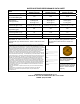
WATER SOFTENER PERFORMANCE DATA SHEET Avantapure 269-869-100-1040 10.0 Avantapure 269-869-125-1047 13.5 Avantapure 269-869-150-1054 12.5 8.0 15.0 15.0 10,600 @ 2.47 23,090 @ 9.06 27,918 @ 13.18 14,922 @ 3.0 32,503 @ 11.0 39,299 @ 16.0 17,906 @ 3.6 39,003 @ 13.2 47,158 @ 19.2 Rated Efficiency (grains/lb Salt @ lb of salt) 4,288 /lb. salt @ 2.47 lbs. 4,974 /lb. salt @ 3.0 lbs. 4,974 /lb. salt @ 3.6 lbs. Maximum Flow Rate During Regeneration (gpm) 2.8 2.8 2.
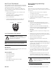
How To Use This Manual General Warnings and Safety Information This installation manual is designed to guide the installer through the process of installing and starting conditioners featuring the AvantaPure series controllers. Electrical This manual is a reference and will not include every system installation situation. The person installing this equipment should have: There are no user-serviceable parts in the AC adapter, motor, or controller. In the event of a failure, these should be replaced.
• Keep the media tank in the upright position. Do not turn upside down or drop. Turning the tank upside down will cause media to enter the valve. • Operating ambient temperature is between 35F (1C) and 120F (49C). • Operating water temperature is between 35F (1C) and 100F (38C). • Working water pressure range is 20 to 125 psi (1.38 to 8.6 bar). In Canada the acceptable working water pressure range is 20 to 100 psi (1.38 to 6.89 bar). • Use only regenerant salts designed for water softening.
Equipment Installation Control Layout Valve Layout AvantaPure Controller LCD Display One Piece Valve Disc Spring Valve Discs Control Module Mount PM MIN LBS KG x100 Down Button Set Button Injector and cap Refill Controller Regenerant Tube Connection Manual Regen Button Up Button AC Adapter (low voltage) Input Chlorine Generator Outlet Optical Sensor Motor Camshaft Main Motor & Optical Sensor Connection Outlet For Future Use Turbine Input or Dry Contact Signal Input Figure 3 Drain Inlet Ba
System Specifications Item Number 4001428 4001429 4001430 Recharge Style Upflow Upflow Upflow Model Number 269-869-100-1040 269-869-125-1044 269-869-150-1054 Media Tank Size 10" x 40" 10" x 44" 10" x 54" Resin Volume 1 ft3 1.25 ft3 1.5 ft3 Recharge (Salt) Tank Size 15" x 40" 15" x 40" 15" x 40" Salt Storage 240 lbs 240 lbs 240 lbs Drain Water Rate 2.7 gpm 2.7 gpm 2.
Location Selection Outdoor Locations Location of a water conditioning system is important. The following conditions are required: The AvantaPure system is designed to be installed indoors. A protected environment is recommended. • Level platform or floor. • Room to access equipment for maintenance and adding regenerant (salt) to tank. When the water conditioning system is installed outdoors, several items must be considered. o • Moisture – The valve and control are rated for NEMA 3 locations.
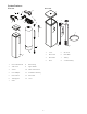
System Features Brine Tank Resin Tank 13 5 1 4 8 6 2 7 3 3 9 10 2 7 8 4 5 6 11 12 1 1 Resin Tank Shroud 8 Brine Fitting 2 Tank Cover 9 Upper Basket 3 Shield 10 Power Transformer 4 Hose Adapter 11 Distributor Tube Assy 5 Flow Control 12 Resin Tank 6 1265 Bypass 13 Cover 7 Valve 9 1 Cover 5 Air Check 2 Brine Tank 6 Brine Well 3 Brine Valve 7 Tubing 4 Float 8 Overflow Fitting
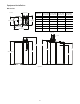
Equipment Installation Dimensions In (cm) 10.6 (26.9) Dimension 10 x 40" Tank (25 x 102 cm) 10 x 44" Tank (25 x 112 cm) 10 x 54" Tank (25 x 137 cm) 10 x 54" Filter (25 x 137 cm) A 39.9 (101) 43.9 (111) 53.9 (137) 53.9 (137) B 47.4 (120) 51.4 (130) 61.4 (156) 61.4 (156) C 43.2 (110) 47.2 (120) 57.2 (145) 57.2 (145) D 41.6 (106) 45.6 (116) 55.6 (141) 55.6 (141) E 33.7 (85.6) 33.7 (85.6) 33.7 (85.6) — F 37.8 (96) 37.8 (96) 37.8 (96) — 17.1 (43.4) 14.9 (37.8) 14.8 (37.
Typical System Layout Bath Tub Lavatory Toilet Outside Faucet Kitchen Outside Faucet Hot Water Outlet Water Heater Laundry Tubs Pump or Meter Floor Drain Figure 5 Standard Basement Before Installation. Cold water lines shown. Bath Tub Lavatory Toilet Outside Faucet Kitchen Outside Faucet Hot Water Outlet Grounding Strap Soft Water Hard Water Bypass Drain Line Water Heater Softener Pump or Meter Laundry Tubs Brine Tank Overflow Drain Floor Drain Figure 6 Softened Water Flow Diagram.
Inspection To Assemble the Media Tank: 1. Stand the tank up and in position. The AvantaPure system is shipped with several parts unassembled. When parts are removed from the packing, they should be inspected for damage. If any parts are damaged or missing, contact your supplier. 2. If the floor under the media tank is uneven, level as needed. WARNING: The media tank contains loose particles that will shift. If the tank is turned upside down or laid back quickly, the particles may enter the valve.
Installation Instructions Note: Before turning on the water to the valve, rotate the two handles on the bypass valve 2-3 times. This will help seat the O-rings and prevent leaking. The 269 conditioner should be installed by someone familiar with plumbing practices. The conditioner is located after the pressure tank (or incoming water supply) and any filtration equipment. Water that leaves the conditioner will feed the hot water heater and the rest of the building.
Drain Line Connection Regenerant Line Connections The regenerant line from the tank connects to the valve. Make the connections and hand tighten. Be sure that the regenerant line is secure and free from air leaks. Even a small leak may cause the regenerant line to drain out, and the conditioner will not draw regenerant from the tank. This may also introduce air into the valve causing problems with valve operation. Note: Standard commercial practices are expressed here.
Electrical Connection Note: Once the tubing has been pushed into the nut it cannot be pulled out. The nut will need to be removed. See Figure 14 for correct assembly. 6. WARNING: This valve and control are for dry location use only, unless used with a Listed Class 2 Power Supply suitable for outdoor use. Hand tighten the nut until the connection is tight. Note: There are no user serviceable parts in the AC adaptor, motor or the control board.
Slow Rinse (Downflow) – Cycle C3a System Operation Water flow moves the regenerant through the resin at a specific rate and rinses to the drain. The resin is regenerated. Treated Water (Downflow) Untreated water is conditioned as it flows through the resin bed and up the riser. The 269 upflow conditioner is a system that will refill the salt tank at the start of a regeneration cycle.
Valve Camshaft Valve Operation The front end of the camshaft has an indicator cup. The cup has slots in the outer periphery and numbers on the inside face (Figure 17). 6 Rinse Drain 4 Outlet Valve 2 Bypass Valve The numbers can be seen with the cover off, from the front over the top of the controller. The number at the top indicates which regeneration cycle is currently in progress.
Sodium or Calcium Hypochlorite AvantaPure Controller These materials are satisfactory for use with polystyrene resins, synthetic gel zeolite, and bentonites. Power Loss Memory Retention The controllers feature battery-free time and date retention during the loss of power. This is designed to last a minimum of 8 hours depending on the installation. The controller will continue to keep time and day in dynamic memory while there is no AC power. 5.
Display Icons 9 Keypad - Button 10 1 2 3 PM MIN LBS KG x100 7 6 8 1 4 2 4 3 5 Button Note: In normal operation and during programming, only a few of the icons will actually be displayed. Function Scroll down through a list. 1. Displays amount of conditioning capacity remaining. 2. "PM" indicates that the time displayed is between 12:00 noon and 12:00 midnight (there is no AM indicator). PM indicator is not used if clock mode is set to 24-hour. 3. Down Press to accept a setting.
Things You Might Need to Know • When the controller is first plugged in, it may display a flashing Err 3 and scrolling "Call Dealer for Service" message. This means that the controller is rotating to the home position. The Err 3 will clear when the control reaches the home position. • The preset default time of regeneration is 2:00 AM. If you want to change it, see the Level II Programming section. • The controller can be programmed to regenerate on specific days of the week.
Level I Programming Table 1 The AvantaPure control can be quickly programmed by following the sequential procedure. Level I program parameters are those that can be accessed by pressing the UP or DOWN buttons. This table is for reference only. Your model number should be set by an AvantaPure Water Treatment Professional based on your specific application requirements. • Model Number: Select a model from the table based on the application. Review Table 1 and determine your model number before you start.
Scrolling Display Buttons to Press Select MODEL NUMBER press then or press or Time of Day 3. Day of Week Set to actual day of the week. SU, MO, TU, WE, TH, FR, SA or 4. Time of Regeneration Set to desired time of regeneration. The time will flash. Full 24 hours. Increments of 1 minute. press then The range is 1-99 however, only the model selections in the table above are valid selections. or press Regeneration Time 1.
Level II Programming Level II program parameters are those parameters used to fine-tune a conditioners operation. These are accessible by pressing and holding the UP and DOWN buttons until the display goes blank. Then release the buttons. Calendar Override is the first Level II parameter displayed.
Scrolling Display Enter Calendar Override Salt Amount Capacity K Grain Hardness GPG Select Language Buttons to Press press then or press LOCKED press then 4. Hardness Grains per Gallon Set based on measured hardness. 3-200 or 5. Display Language Scroll and select banner language. 1-8 or 6. Clock Select 12 hr or 24 hr. 12 or 24 or 7. Units of Measure Select English or Metric.
Level lll Cycle Programming Historical information can be retrieved from the controller be pressing the SET and DOWN buttons simultaneously, with the controller in the home position. Release both buttons when the controller displays MODEL NUMBER. Press the UP or DOWN buttons to navigate to each setting. The readout will scroll across the top of the display and the value will be displayed below the readout.
Placing 269 Water Conditioning System Into Operation (Fill Brine Tank First) 5. Advance the control to the Backwash cycle (C1). See Cycle Sequence Table. Cycle Sequence Table Quick Cycling the Analyzer Control It is required that the control be quick cycled to specific regeneration cycles when placing the conditioner into operation. Please review the following instructions for quick cycling the control before proceeding to start-up. 1. 2.
8. Press and hold the SET and UP button for 5 seconds to cancel regeneration, and cycle the control back to the service position. 9. Start another regeneration. Advance the controller to the brine refill position (C8) to prime the line between the regenerant tank and the valve (conditioner only). A. Slowly open the main water supply valve again to the fully open position. Be sure not to open too rapidly, as that would push the media out of the media tank.
AvantaPure Valve Exploded View & Parts List 7 9 11 12 6 5 8 B Y PA S 13 S 4 3 10 21 B Y PA S S 20 22 2 14 15 23 1 12 17 24 18 19 28 16
Item 1 Part Number Description 3001745 AvantaPure Control Qty. Item Part Number 1 12 1030502 Ball, Flow Restrictor 12 1 13 Not Included Adapter Kit, Multiple Options 1 Description Qty.
Resin Tank Assembly and Parts List 2 5 3 7 1 6 4 Item Part Number 1 CH30491-01010101-30 Tank, 10 x 40, Universal Inlet, Natural Color, Composite Base CH30523-01010101-30 Tank 10 x 44, Universal Inlet, Natural Color, Composite Base CH30579-01010101-30 Description Qty.
Brine Tank and Brine Well (CH15676) Assembly Exploded View & Parts List 11 5 3 2 1 6 9 4 10 7 8 8 Item Part Number 1 CH15013-2 Brine Well w/Slots 1 2 CH15062 Safety Brine Valve 1 3 CH15070 Grommet 2 4 CH16371-60 5 CH15024 6 CH15064-1 7 CH15063-2 Air Check Assembly 1 8 BR10332 Tubing Insert, Brass 2 9 CH20774 Overflow Fitting Assembly 1 CH15031-1 Overflow Elbow 1 CH15031-2 Overflow Nut 1 CH16331 Description Qty.
Troubleshooting AvantaPure Controller Troubleshooting Problem Possible Cause Solution ERR 1 is displayed. Program settings have been corrupted. Press any key and reset model number. ERR 3 is displayed. Controller does not know the position of the camshaft. Camshaft should be rotating to find Home position. Wait for two minutes for the controller to return to Home position. The hourglass should be flashing on the display indicating the motor is running. Camshaft is not turning during ERR 3 display.
System Troubleshooting Problem 1. Brine tank overflow. 2. Flowing or dripping water at drain or brine line after regeneration. 3. Hard water leakage after regeneration. 4. Control will not draw brine. Possible Cause Solution a. Uncontrolled brine refill flow rate. b. Air leak in brine line to air check. a. Remove brine control to clean ball and seat. b. Check all connections in brine line for leaks. Refer to instructions. c. Drain control clogged with resin or other debris. c. Clean drain control.
9. Intermittent or irregular regenerant draw. 10. No conditioned water after regeneration. 11. Backwashes or purges at excessively low or high rate. 12. No water flow display when water is flowing. 13. Run out of conditioned water between regenerations. a. Low water pressure. b. Defective injector. a. Set pump to maintain 20 psi at conditioner. b. Replace injector. (Contact dealer.) a. No regenerant in regenerant tank. b. Injector plugged. a. Add regenerant to regenerant tank. c.
Pentair Residential Filtration, LLC 5730 North Glen Park Road Milwaukee, WI 53209-4454 USA (262) 238-4400 Phone (262) 238-4402 Fax ©2011 Pentair Residential Filtration, LLC P/N 4001404 Rev A JE11