
Operating instructions


4
How To Use This Manual
This installation manual is designed to guide the installer
through the process of installing and starting conditioners
featuring the AvantaPure series controllers.
This manual is a reference and will not include every
system installation situation. The person installing this
equipment should have:
• Training in the AvantaPure series controllers and
Autotrol brand valves
• Knowledge of water conditioning and how to
determine proper control settings
• Basic plumbing skills
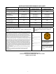
• The directional instructions "left" and “right" are
determined by looking at the front of the unit.
Figure 1
Icons That Appear In This Manual
WARNING:
Failure to follow this
instruction can result in personal injury or
damage to the equipment.
Note:
This will make the process easier if followed.
Introduction
Inspect the unit for damage or missing parts. Contact your
supplier if any discrepancies exist.
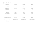
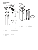
Parts Included
•Resin Tank with Valve
•Brine Tank with Cover
• Power Transformer
• Water Bypass
• Hose Adapter and Flow Control in a bag
• Brine Well Assembly
General Warnings and Safety
Information
Electrical
There are no user-serviceable parts in the AC adapter,
motor, or controller. In the event of a failure, these should
be replaced.
• All electrical connections must be completed
according to local codes.
• Use only the power AC adapter that is supplied.
• The power outlet must be grounded.
• To disconnect power, unplug the AC adapter from its
power source.
Mechanical
• Do not use petroleum based lubricants such as
vaseline, oils, or hydrocarbon based lubricants. Use
only 100% silicone lubricants.
• All plastic connections should be hand tightened.
Teflon tape may be used on connections that do not
use an O-ring seal. Do not use pliers or pipe
wrenches.
• All plumbing must be completed according to local
codes.
• Soldering near the drain line should be done before
connecting the drain line to the valve. Excessive heat
will cause interior damage to the valve.
• Observe drain line requirements.
• Do not use lead-based solder for sweat solder
connections.
• The drain line must be a minimum of 1/2-inch
diameter. Use 3/4-inch pipe if the backwash flow rate
is greater than 7 GPM (26.5 Lpm) or the pipe length is
greater than 20 feet (6 m).
• Do not support the weight of the system on the
control valve fittings, plumbing, or the bypass.
• It is not recommended to use sealants on the threads.
Use Teflon
a
tape on the threads of the 1-inch NPT
elbow, the drain line connections, and other NPT
threads.
• Install appropriate grounding strap across the inlet
and outlet metal piping of the water conditioning
system to ensure that a proper ground is maintained.
WARNING:
Dry location use only, unless
used with a Listed Class 2 Power Supply
suitable for outdoor use.
General
• Observe all warnings that appear in this manual.
Left Side Right Side
a. Teflon is a trademark of E.I. duPont de Nemours.