G E ZON E LIN E ® Packaged Terminal Air Conditioners ARCHITECTS & ENGINEERS DATA MANUAL AZ45/AZ65 SERIES
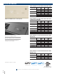
Q UI C K R E F ER E N C E AZ45 SERIES COOLING WITH ELECTRIC HEAT MODEL NUMBER AZ45E07DAB AZ45E09DAB AZ45E12DAB AZ45E15DAB AZ45 and AZ65 series control panel VOLTAGE COOLING (BTUH) EER COOLING WATTS* 208 7,000 13.4 520 230 7,200 13.4 535 208 9,600 12.1 790 230 9,700 12.1 800 208 11,500 11.8 900 230 11,600 11.7 960 208 14,500 10.5 1,405 230 14,600 10.
QU I C K R EF E R E N C E AZ65 SERIES HEAT PUMP WITH BACKUP ELECTRIC HEAT MODEL NUMBER AZ65H07DAB AZ65H09DAB AZ65H12DAB AZ65H15DAB VOLTAGE COOLING (BTUH) EER 208 230 208 230 208 230 208 230 6,900 7,100 9,600 9,700 11,800 11,900 14,200 14,400 13.0 13.0 12.2 12.2 11.9 11.7 10.6 10.6 COOLING HEAT PUMP WATTS (BTUH)* 530 545 785 795 1,000 1,015 1,335 1,355 6,100 6,200 8,000 8,100 10,300 10,400 13,300 13,400 COP HEAT PUMP WATTS* 4.0 4.0 3.7 3.7 3.6 3.6 3.3 3.
H E AT ER WAT TAGE A N D P OWER CONNECTI ON KI TS Power connection kits are required on all Zoneline chassis. (See chart.) The correct kit for the installation is determined by the voltage and amperage of the electrical circuit and the means of connecting the unit to the building wiring. If the unit is to be plugged into a receptacle, a line cord kit would be used; if the unit is to be permanently connected, a direct connector or a permanent connection kit would be used.
TAB L E OF CO N TE N TS Mini Specs AZ45 and AZ65 Series .............................................................2–3 Mini Specs Power Connection Kits & Nomenclature ............................. 4 Table of Contents.......................................................................................................5 Introduction..................................................................................................................6 The Zoneline® System.........................................
IN T R O D U C T IO N This manual is designed for use in design and selection of zoned comfort control systems utilizing GE Appliances Zoneline Packaged Terminal Air Conditioners (PTAC) and Packaged Terminal Heat Pumps (PTHP). It provides product, performance and application information to our customers as well as architects and engineers.
T HE ZO N E LIN E ® SYSTE M The typical Zoneline® installation consists of the wall sleeve, chassis, power cord and exterior grille. Some installations may use a sub-base for support of the unit or for ease of electrical connections. Each of the components should be the standard products offered by GE Appliances. Custom exterior grills should be approved by GE Appliances Applications Engineering.
ZO NE L I N E ® FE ATUR E S RESISTANCE HEAT HEAT PUMP AZ45 SERIES AZ45 DRY AIR 25 AZ65 SERIES Cooling EER range (230 Volts/265 Volts) 10.5 - 13.4 11.0 - 12.8 10.3 - 13.0 Heating COP range (230 Volts/265 Volts) N/A N/A 3.2 - 4.
G E ZON E L IN E ® WITH M a ke up Air Add the benefit of our second generation of Makeup Air to the industry’s most trusted PTAC, with GE Zoneline® Makeup Air. Factory-installed and tested, the Makeup Air module is an independent secondary system that provides outdoor air continuously. FEATURES • Dedicated fans in the Makeup Air system that are adjustable to 6 pre-set fan speeds from 25 to 50 CFM. • Provides outdoor air anytime the unit is plugged into the power source (even if unit is turned off).
THE ZONELINE AZ45 AND AZ65 SERIES have changes suggested by customers and enhancements from GE Appliances Engineering to make product improvements and meet the changing environment. • Quieter Operation • Ease of access—fewer screws and number of parts • Make up air module • Cross-flow blower across the product line for quieter operation See the “Features and Benefits” section for in-depth explanation of these changes and the industry-leading features of GE Appliances Zoneline retained from previous series.
FFEATURES E AT U R E S&&BENEFITS B E N E F ITS STANDARD PHYSICAL DIMENSIONS GE Appliances has maintained the same wall sleeve dimensions since 1961—42" wide x 16" high x 13-3/4" deep—making replacement of older units easy. WEATHER RESISTANT SYSTEM SEAL Per AHRI, the air infiltration rate shall not exceed 19.3 CFM at the perimeter of the wall sleeve where it normally projects through the wall.
FE AT U R ES & B E N E F ITS (CONTINUED) COMPRESSOR RANDOM RESTART In the event of a power failure, all compressors attempting to restart immediately when power is restored can result in a power surge that can cause another power interruption. The microprocessors in the Zoneline units have a random restart logic system that prevents all units from starting at the same time. ROTARY COMPRESSOR Provides smoother operation for quiet, dependable service. GE Appliances has used rotary compressors since 1961.
F E AT U R E S & B E N E F ITS (CONTINUED) CONCEALED MANUAL VENT CONTROL An open ventilation door on GE Appliances Zoneline® packaged terminal air conditioners and heat pumps allows outside air to enter the room through a screen-covered opening in the weather barrier that separates the indoor and outdoor sections of the unit. A concealed lever, located along the left side of the unit under the front cover, is used to open and close the vent door.
AUX I L I A RY CO N TR O L-AUX SE T BUTTON The auxiliary control push button is located behind the room cabinet, below the control panel. The auxiliary controls come preset to the modes most desired by customers. However, the owner is responsible for ensuring the auxiliary controls are set to the desired function. There are up to 12 different modes that can be set using the auxiliary set button. TO CHANGE MODES: • Press the MODE button until the unit is turned OFF (or turn off the remote thermostat).
“Mode” AUXI L I ARY CO N TR O L SE TTINGS (CONTINUED) Mode 4—Constant ON fan The default setting for Mode 4 is OFF. NOTE: Constant fan “on” runs the indoor fan continuously at high speed—even if the unit is turned off.
CE NT R A L D E SK CO N TR O L Some installations may want to govern the ability of the unit to operate from a control device remote to the unit or even remote to the room in which the unit is located. The general term given to systems such as this is Central Desk Control (CDC). The most common installation of this type of system is a switch mounted at the registration desk and, upon guest check-in, a button is pushed or a switch is moved to allow the air conditioner to operate.
RE M OT E T H E R M OSTAT CO N TROL In many installations, control of the operation of the unit at a location remote from the unit itself is desired. A unit mounted high in the wall or over a door, for instance, where the unit-mounted controls are inaccessible, can be connected to a wall-mounted thermostat. Other installations may use remote thermostat control for design or performance enhancement.
R E MOT E T H E R MOSTAT CO N TROL (CONTINUED) HEAT PUMP MODELS The Zoneline AZ65 Series heat pump units may be connected to a single-stage cooling/two-stage heating thermostat designed for use with heat pump systems.
RE M OT E T H E R M OSTAT CO N TROL SELECTI ON CHART FOR ZONELINE ® PAC KE D T E R MIN A L UN ITS GE Appliances also offers the RAK180W1 universal thermostat that offers occupancy sensing energy management. This thermostat is set up for two stage heating systems (AZ65) out of the box, but also works on single stage heating systems (AZ45) with changes to the thermostat configuration settings.
H E AT P U M P S & E N E R GY SAVINGS Heat pumps save energy and cost less to operate than units with electric resistance heaters as the only heat source. Just as the EER (Energy Efficiency Ratio) of an air conditioner is an indication of the efficiency of the unit, COP (Coefficient of Performance) is the indication of the efficiency of the heat pump. This relative efficiency of a heat pump compares the unit to electric resistance heat. If a unit has a COP of 3.
HE AT P U M P S & E N E R GY SAVINGS (CONTINUED) HEAT PUMP OPERATION—ZONELINE AZ65 SERIES Heat sources: Heat pump, heat pump with partial electric resistance heat, or electric resistance heat. Zoneline heat pumps employ a highly featured microprocessor control system interfaced with thermistors to accurately measure indoor air temperature, outdoor air temperature, indoor coil temperature and outdoor coil temperature.
A PP L I C AT I ON CO M ME N TS It is important that any air conditioning system be properly sized and applied in order to achieve the desired temperature and humidity levels in the space to be conditioned. Zoneline units are designed primarily to provide heating and cooling with the additional benefit that during operation in the cooling mode, the units also remove some moisture from the conditioned space.
WA L L S L E EVE DIM E N SIO N S RAB71* SLEEVE ADDITIONAL WALL SLEEVE DEPTHS RAB7116B - 16" RAB7118 - 18” RAB7120 - 20” RAB7124B - 24" 42" 1/2" SQ. HOLE (2 REQ'D.) A " 3/4 13- 2-55/64" 1/4" DIA 1/2" 1-1/2" TYP 9-41/64" 16" 4" 8" WALL OPENING 16-1/4" MIN. x 42-1/4" MIN. 21" 1/2" DIA. HOLE (2 REQ'D.) 34" RAB77* WALL SLEEVE 42-1/8" 13-7/8" 2-7/8" 1-1/2" 1/2" SQ. HOLE (2 REQ'D.) 9/16" 16-1/4" 6" WALL OPENING 16-1/2" MIN. x 42-3/8" MIN. 1/2" DIA. (3 REQ'D.
WA L L S L E EVE A choice of wall sleeves is available for Zoneline® units. RAB71B — This insulated sleeve is constructed of heavygauge galvanized steel and finished with a baked-enamel finish for protection and appearance. Design of the sleeve provides for support of the chassis and free draining of any water entering the wall sleeve. A petroleum microcrystalline wax is applied at critical points of fabrication to seal against moisture.
WA L L S L E EVE IN STA LLATIO N DATA (CONTINUED) of 250 volts be “permanently connected.” There are also some installations where units connected to voltage sources under 250 volts may also need to be “permanently connected.” If you are in doubt about the requirements for a particular installation, consult Article 440 of the NEC or the local electrical inspector. These requirements are designed to protect personal safety and should be strictly followed.
WA L L S L E EVE IN STA L LATIO N DATA SUB-BASE (CONTINUED) For new construction, early planning with the architect is necessary. Unit location, electrical connection locations and wall openings of the proper dimensions are essential to avoid the necessity of rework, fillers, framing, moving electrical outlets and other expensive modifications. For existing construction, it is important that carpentry, masonry and electrical work be performed by competent, qualified personnel.
WA L L S L E EVE IN STA LLATIO N DATA PREPARATION OF THE WALL SLEEVE FOR ALL TYPES OF CONSTRUCTION Do not remove the stiffener from inside the wall sleeve or the weather closure panel from the outside face of the wall sleeve until the outdoor grille and chassis are ready to be installed. 1. Position the wall sleeve into the wall.
HEADER – 4" x 4" OR 2 - 2" x 4" ON EDGE CRIPPLE Figure 1 SUB-FLOOR FINISHED FLOOR Note: Do not remove the stiffener support from inside the wall sleeve until the chassis is to be installed. 16-1/4" MIN. RAB7B 16-1/2" MIN. RAB77B ADJUSTABLE FRAMING TO SECURE THIS DIMENSION 42-1/4" MIN. (RAB71)† 42-3/8" MIN. (RAB77)† JACK STUDS MAIN STUD †WORKS FOR ALL RAB71 OR RAB77 SERIES WALL SLEEVE JACK STUD FRAMING FOR WALL SLEEVE Brick Veneer and Frame Construction 2" MIN.
WALL RECEPTACLE (BY OTHERS) 2" MIN. CAULK* CAULK* 1/4" MIN. RAG60 1/4" RAG61, 62, 63 1-3/8" RAG67 1-1/4" POWER SUPPLY CONDUIT WALL Sleeve OUTDOOR GRILLE STEEL LINTEL FINISHED FLOOR OR TOP OF CARPET 3" MIN. 5" MAX. RAB71B 13-3/4" RAB77B 13-7/8" SIDE CHANNEL 2-3/8" WALL Sleeve POWER SUPPLY CONDUIT (ALTERNATE ENTRY) CAULK* 2" MIN. RAB71B 16" RAB77B 16-1/4" MOUNTING SCREWS BY INSTALLER 20-13/16" (RAB71B) 20-15/16" (RAB77B) CAULK* 2-3/8" Min.
USE NO SCREWS IN BOTTOM OF Sleeve OUTDOOR GRILLE Gasket and caulk around perimeter of wall sleeve all four sides where it joins the building WALL SECTION – DETAILED SIDE VIEW MIN.
2-1/2" ROOM CABINET See page 45 for line cord length. ELECTRICAL RECEPTACLE (BY OTHERS). FLUSH MOUNTED. D C CAULK* A CAULK* FRONT VIEW LINTEL ADJACENT WALL RAB71B 13-3/4" RAB77B 13-7/8" *Caulk around perimeter of wall sleeve all four sides where it joins the building - Interior and Exterior. TOP VIEW 27-1/4" ROOM CABINET Sleeve RAB71B 42" RAB77B 42-1/8" WALL OPENING 16-1/4" x 42-1/4" MIN. FOR RAB71B 16-1/2" x 42-3/8" MIN.
METAL SLEEVE EXTENSION FOR WALLS DEEPER THAN 13-1/8" (11-1/8" WITH SUB-BASE) 2" MIN. 1-1/2" (4 SIDES) 13-3/4" + D" FLASHING (FIELD SUPPLIED) RAB71B/77B WALL Sleeve SPLITTER BETWEEN AIR INTAKE AND DISCHARGE " /8 -5 10 ± 1" WIDE 45° DRIP LIP " 1/4 FLANGES AND DRAIN HOLE LOCATIONS SAME AS ON WALL Sleeve SEALANT - ALL FOUR (4) FLANGES 6-1/4" ± 1/4" CAULK* ALL 4 SIDES CUT DRAIN SLOTS IN BOTH FLANGES (FOUR REQUIRED) TO MATCH DRAIN HOLES IN RAB71B/77B D AS REQ'D. RAB71B/77B Sleeve EXT.
A D A C B DIMENSIONS: A. DISTANCE FROM GRILLE OR Sleeve TO OUTSIDE SURFACE OF WALL PLUS 2" TO 4" (TO INSERT UNDER Sleeve). B. 1" DRIP LIP (MINIMUM) C. 42" PLUS - SUFFICIENT TO FIT SNUGGLY UNDER AND UP AROUND THE Sleeve. D. 2" MINIMUM (CAUTION: WHEN CAULKING DO NOT BLOCK DRAIN HOLES IN Sleeve OR GRILLE.) IF GRILLE IS TO BE MOUNTED TO WALL SURFACE "A" SPLITTERS MUST BE USED. (SEE PAGE 32.
7.70" 7.70" 12-7/8" KNOCKOUTS (ENCLOSURE) 4 REAR; 4 BOTTOM 12-3/4" 42" FRONT VIEW BACK VIEW 5.15" LEVELING SCREW *SHOWN WITH ACCESS COVERS REMOVED. NOTE: CAUTION - REMOVE KNOCKOUTS FROM INSIDE OUT. INTERIOR ADJACENT WALL D RECOMMEND 2" TO INTERIOR ADJACENT WALL BOTH SIDES. 5.15" FINISHED INTERIOR WALL 2-3/8" MIN. 13" SMALL 7/8" DIA. 7/8" SEE NOTE LEFT SIDE D C RAB71B 16" RAB77B 16-1/4" C CAULK* A 2-3/8" MIN.
6" TYPE “C” SCREW TO SECURE SIDE CHANNELS TYPE “A” SCREW SCREW CLIP TYPE “D” 6 REQ’D. TYPE “A” 2 REQ’D. TYPE “B” 8 REQ’D. TYPE “C” USE WITH RAB71B USE WITH RAB77B TYPE “D” TYPE “E” SUB-BASE MOUNTING CLIP TYPE “E” MOLDED Sleeve Electrical wiring may enter the sub-base through any of the knockout holes provided in the sub-base. Knockout holes in the sub-base access plate may accommodate a receptacle, which allows the use of a power cord (if permitted by code for the particular installation).
CON D EN SAT E DISP OSA L SYSTEMS COOLING CONDENSATE Air conditioners produce condensate water as a result of lowering the humidity of the area being conditioned. When the indoor coil temperature is below the dew point, moisture in the air condenses into water droplets on the indoor coil. This water drains to a pan located under the indoor coil and is routed through the weather barrier or bulkhead (the partition separating the indoor and outdoor sides of the unit) to the base pan on the outdoor side.
“A” “B” 1/2" O.D. 90° ELBOW DRAIN TUBE SQUARE DRAIN HOLES SEE PAGE 38 NOTE #6 STEEL MOUNTING PLATE NEOPRENE SPONGE GASKET USE TYPE “A” SCREW FOR METAL Sleeve (RAB71B) AND TYPE “B” SCREW FOR MOLDED Sleeve (RAB77B) PLASTIC NOTE: Drain kit using either the 90° elbow tube or the straight tube may be installed without modification when using RAG60 exterior grille. Drain kit using the 90° elbow tube may be installed without modification when using RAG61 through RAG63 exterior grilles.
“B” PLASTIC COVER PLATE 1/2" OD TUBE GASKET 5. With the RAD10 the two square drain holes in the bottom outer flange of the wall sleeve are sealed by the gaskets and mounting plates shown above. 6. Two 1/2" diameter holes located 1/4" above the sleeve bottom in the bottom outer flange provide overflow drainage to the outdoors when wind-driven rain enters the chassis.
D U C T E D I N STA LLATIO N S AZ45 AND AZ65 SERIES ZONELINE® UNITS MAY BE USED IN DUCTED INSTALLATIONS. With a ducted installation it is possible to condition the air in two areas that have a common wall separating them. A special adapter mounts on the wall sleeve and a transition piece directs the air from the unit into the adapter duct. Instructions for mounting the adapter to the wall sleeve are included with the duct adapter.
Notes: 1. RAK6053 kit includes duct adapter, transition and mounting hardware. 2. RAK601B duct extension may be installed at either end of the RAK6053 duct adapter. Maximum duct extension length is 15'. Duct extension must be field fabricated for installations where length of duct exceeds length of RAK601B (44"). Field-fabricated duct extension must be insulated to prevent condensation from forming on exterior. Duct extension may not contain bends or turns. 3.
FINISHED FLOOR 10" ROOM CABINET TRANSITION DUCT RAK6053 ADAPTER WALL Sleeve 3/4" MIN. WALL TO Sleeve EDGE CAULK 12-3/4" MAX. *Caulk around perimeter of wall sleeve all four sides where it joins the building - Interior and Exterior. RECEPTACLE CAULK* (BY OTHERS ALT. LOCATIONS) 16-1/8" 2-29/32" 7-3/32" 6-1/2" ANY CONSTRUCTION RAG60 - 1/4" RAG61-63 - 1-3/8" RAG67 - 1-1/4" CAULK* CAULK 1/4" MIN. 3" MIN. 5" MAX. ROOM CABINET TRANSITION DUCT RAK6053 ADAPTER 3-11/16" RAK204 *2-3/8" min.
DUC T E D I N STA L LATIO N S (CONTINUED) The design of the Zoneline chassis has changed over the years to provide better performance and appearance, therefore, some of the components used in ducted applications have changed. Select the proper components from the information below. The best procedure in determining the correct kit is to measure the existing duct extension cross section.
E X T ER I O R A R C HITE C TUR A L TREATMENTS AND SPECI AL OU T D O O R GR ILLE S The architectural design of a building may dictate the use of special or oversized louvers for aesthetic reasons.
POWE R CO N N E C TIO N F O R AZ45 AND AZ65 SERI ES ZONELI NE® UNITS (CONTINUED) 230/208 VOLT PERMANENTLY CONNECTED UNITS The short sub-base line cord may not be used without the sub-base and junction box. the RAK4002D forms an enclosed junction box on the chassis. The RAK4002D has a hole to allow a 1/2" trade size electrical conduit and a square knockout for the chaseway to be connected to the junction box.
POW ER CON N E C TIO N F O R AZ45 AND AZ65 SERI ES ZONELI NE® U NITS (CONTINUED) ELECTRICAL WIRING INFORMATION – AZ45/AZ65 SERIES All Zonelines are single-phase 60-hertz units. are shown on pages 43–44. Branch circuit ampacity and electrical protective device sizing are shown on pages 43–44 for 230/208-volt and for 265-volt units.
N OR M A L Y E AR LY O P E R ATIN G DATA (Cooling Hours based on 75°F indoor temperature with air conditioner sized to meet the design conditions.
G-12 1 1 1 R-16 N-16 Y-16 W-16 B-16 R-16 N-16 Y-16 W-16 B-16 ‘MUAM’ GND ‘OD COIL’ GND ‘BASEPAN TO SLEEVE’ GND OUTDOOR FAN J304 J305 1 2 J104 J103 1 2 1 2 3 4 5 6 1 2 3 4 5 6 FOR “ICR” OR “MUAM” CONNECTOR FOR REVERSING VALVE CONNECTOR J406 2 (MAKE-UP AIR MODULE COMPRESSOR POWER) J305 ON MAIN BOARD 1 1 J405 1 2 3 CDC/EXT.
S UG G EST E D B ID F O R M SP E C IFI CATI ONS The following are suggested specifications for the Zoneline® AZ45 Series Packaged Terminal Air Conditioner and the AZ65 Series Packaged Terminal Heat Pump. The contractor will furnish packaged terminal air conditioners of the sizes and capacities shown on the schedule and in the specifications. The units shall be located as shown on the drawings and each shall consist of a chassis, room cabinet, wall sleeve, sub-base if specified, and outdoor grille.
SU G G EST E D B ID F O R M SP E CI FI CATI ONS Heat pump unit shall include reverse cycle defrost that automatically begins a defrost cycle when hardware and software determines the criteria for defrosting has been met.
AZ65 S ER I E S SP E C IF IC ATIO N S COOLING Room air conditioner sizing is all about matching the room size to the air conditioner size. Since air conditioners remove both heat and humidity from the air, a unit that is too large, will cool the room before it has a chance to remove the humidity. The result will be a room that's not very comfortable – cool, but feeling damp and clammy. Most musty odors in rooms are due to excess humidity.
G E NE R AL IN STA L LATIO N SUGGESTI ONS Many times poor or non-existent caulking around the exterior of the wall sleeve results in air infiltration, causing the unit to run excessively. One way to check for air infiltration is to look under and around the unit to the outdoors. If you can see light, there is air infiltration. The first floor of a building is where this problem most frequently occurs since caulking the bottom of the wall sleeve may require lying outside in the dirt while working.
GE N ER A L I N STA L LATIO N SUG GESTI ONS REPLACEMENT INSTALLATIONS GE offers duct adapters to allow for easy replacements of previous-design chassis in ducted installations where a GE duct adapter was used in the original installation. A duct adapter is available that will align with the duct extension when GE-built components were used in the original installation. The duct adapter/extension used from the early 1960s until late 1987 was 8-3/8" high by 6-1/2" wide.
ZON E L I N E ® C HASSIS N O M E NCLATURE A The Zoneline chassis is identified by a model number defining the type of unit, cooling capacity, electrical information and optional features included on the unit. When specifying or ordering the Zoneline chassis, use of this nomenclature will assure receiving the correct unit.
AZ45 S ER I E S SP E C IF IC ATIO N S 230/208V Models Cooling BTUH EER (BTU/Watt) Dehumidification Pts/Hr Refrigerant type CFM, indoor fan high CFM, indoor fan low Vent CFM (full open)* Power factor Sensible heat ratio @ 230 volts Cooling Watts Cooling Amperes, F.L. Amperes, L.R.
AZ65 S ER I E S SP E C IF IC ATIO NS 230/208V Models Cooling BTUH EER (BTU/Watt) Dehumidification Pts/Hr Refrigerant type CFM, indoor fan high CFM, indoor fan low Vent CFM (full open)* Power factor Sensible heat ratio @ 230 volts Cooling Watts Cooling Amperes, F.L. Amperes, L.R.
ACC E SS ORY L IST KIT NUMBER RAA13 RAA64 RAB71B RAB7116B RAB7118B RAB7120B RAB7124B RAB77B RAB81 RAB81B RAD10 RAG60 RAG61 RAG62 RAG63 RAG67 RAK13 RAK40 RAK164D2 RAK164P2 RAK164F2 RAK180W1 RAK204D15C RAK204D20C RAK204D30C RAK204E15C RAK204E20C RAK204E30C RAK204U RAK205CW RAK315P RAK320P RAK330P RAK315SP RAK320SP RAK330SP RAK4002D RAK315D RAK320D RAK330D RAK515D RAK520D RAK530D RAK515P RAK520P RAK530P RAK601B RAK602B RAK6053 RAK7013 RAK7023 RAKCDC RAKVENT1 DESCRIPTION FOR ADDITIONAL INFORMATION REFER TO PAG
ALP HA B E TIC A L IN D E X Accessory List 56 Application Comments 22 Auxiliary Control Settings Central Desk Control Condensate Disposal Systems Dry Air 25 14–15 16 36–38 10 Ducted Installations 39–42 Exterior Grilles 42–43 Features and Benefits Features Table 8 51-52 Heat Pumps and Energy Savings 20–21 Introduction to Zoneline Units 6 Makeup Air 9 Mini Specs AZ45 Series 2 Mini Specs AZ65 Series 3 Normal Yearly Operating Data Power Connection Kits Remote Thermostat Control Reverse Cyc
N OTE S ARCHITECTS & ENGINEERS DATA MANUAL AZ45/AZ65 SERIES 58
NOT E S ARCHITECTS & ENGINEERS DATA MANUAL AZ45/AZ65 SERIES 59
Appliance Park Louisville, KY 40225 zoneline.com Pub No.