
Data Manual


28
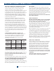
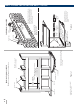
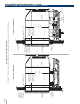
FRAMING FOR WALL SLEEVE
Brick Veneer and Frame Construction
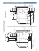
FASTENING WALL SLEEVE
Figure 1 Figure 2
MAIN STUD
JACK STUDS
HEADER – 4" x 4" OR
2 - 2" x 4" ON EDGE
16-1/4" MIN. RAB7B
16-1/2" MIN. RAB77B
ADJUSTABLE FRAMING TO SECURE
THIS DIMENSION
42-1/4" MIN. (RAB71)
†
42-3/8" MIN. (RAB77)
†
JACK STUD
CRIPPLE
FINISHED FLOOR
SUB-FLOOR
Note: Do not remove the stiener support
from inside the wall sleeve until the chassis
is to be installed.
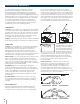
MAIN STUDS
JACK STUD
HEADER
MOUNTING
SCREW HOLE
LINTEL
Framing detail for this construction is as
shown in Figure 1. Note use of lintel under
first course of brick above the Zoneline
sleeve. Do not use the sleeve as a lintel.
Mounting screw holes shown are to be
made by the installer.
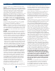
NO HOLES PERMITTED
IN BOTTOM OF Sleeve
(EXCEPTION -RAD10
DRAIN KIT)
Choice of attachment devices
through both ends of sleeve or
the top. Mounting screw holes
and attachment devices by
installer.
MAIN STUD
JACK STUD
2" MIN.
WOOD
SCREW
MOLLY
OR TOGGLE
BOLT
EXPANSION
ANCHOR
BOLT
NO HOLES PERMITTED IN
BOTTOM OF Sleeve
(EXCEPTION - RAD10
DRAIN KIT)
†WORKS FOR ALL RAB71 OR RAB77
SERIES WALL SLEEVE
WALL SLEEVE INSTALLATION DATA (CONTINUED)