
Data Manual

39
AZ45 AND AZ65 SERIES ZONELINE® UNITS MAY
BE USED IN DUCTED INSTALLATIONS.
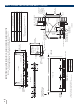
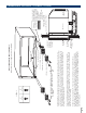
With a ducted installation it is possible to condition the air
in two areas that have a common wall separating them.
A special adapter mounts on the wall sleeve and a transition
piece directs the air from the unit into the adapter duct.
Instructions for mounting the adapter to the wall sleeve
are included with the duct adapter. The adapter contains a
grille that allows air from the unit to be discharged into the
primary room and the adapter connects to a duct extension
that allows the air to flow to the adjoining room. Ducting
a unit may allow a single unit to be used rather than a
separate unit in each room, providing a means of reducing
initial equipment cost. The duct may extend a total of 15
feet (with a field-fabricated insulated duct extension) in one
direction, either to the right or to the left of the unit. A baffle
or damper installed in the discharge duct of the adapter is
provided from the factory to provide approximately 70%
air discharge into the primary room (room in which the unit
is installed) and 30% into the secondary (adjacent) room.
Completely removing the discharge damper will result in
approximately 80% air discharge into the primary room and
20% into the secondary room.
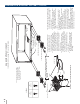
The installation of the wall sleeve and sub-base, if used, is
the same for units being ducted as for free-standing
units. The duct adapter support bracket overlaps the wall
sleeve by 1" and the bracket and mounting screws add
approximately 3/8" (3/16" on each side) to the width of the
wall sleeve. If less than 1" of the wall sleeve projects into the
room it will be necessary to allow for the additional width in
the opening for the wall sleeve. The duct adapter mounting
brackets should be mounted prior to installing the sleeve in
the wall.
Refer to pages 40–41 for drawings of ducted installations.
Prior to the installation of the transition from the room
cabinet to the adapter, it will be necessary to remove the
discharge grille from the room cabinet. Instructions for this
modification are included with the duct adapter.
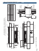
NEW DUCTED INSTALLATIONS
COMPONENTS
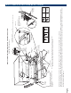
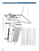
Duct Adapter RAK6053 — The duct adapter is secured
to each side of the wall sleeve and requires the drilling of
mounting holes in the wall sleeve during installation.
A template for the hole
location is in the installation
instructions. By securing the
duct adapter to the wall sleeve,
the chassis retains the slide-out
feature for servicing after
the transition piece is removed.
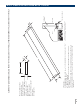
Duct Extension RAK601B — This kit contains a 44"-long
insulated duct, a register mounting collar, and an air supply
register. It can be secured to the duct adapter at either end
of the adapter. This duct may be cut at any dimension and
used in two applications, providing the sum of the two duct
lengths necessary does not exceed the 44" length.
Even in single applications, the mounting flange must be
cut off one end of the duct to accept the collar and supply
register.
Mounting Collar and Supply Register RAK602B —Are
components included in the duct extension kit RAK601B.
They may be ordered separately for installations where
two duct extensions are made from one RAK601B.
DUCTED APPLICATION
CONSIDERATIONS
When designing a ducted application, some application
considerations to be made include:
1. Do not exceed the 15-foot-length maximum for the
duct extension. Field-supplied duct extension must be
completely insulated with minimum of 1/2" insulation.
2. The duct must be a straight run. Turns or bends in the
duct extension create air pressure drops that the unit
is not designed to overcome.
3. Turn the “Duct Mode” on in the auxiliary control
settings (Mode 7). This increases the fan speed to
ensure proper circulation.
4. Minimum recommended clearance between the unit
and the adjacent wall is 2".
5. Provisions for return air must be made to allow air
circulation from secondary room. Doors in both
secondary and primary rooms may be undercut or a
return grille may be installed through a common wall.
6. When calculating the heat gain/heat loss, take both
areas into consideration.
7. Duct adapters are not for use on Dry Air 25 models or
Makeup Air models.
8. For best room temperature regulation, remote
thermostats should be used with Makeup Air models.
9. Heater wattages are reduced in duct mode
(see chart below).
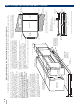
DUCT
ADAPTER
RAK6053
DUCT MODE - HEATER WATTS OUTPUT
(265V AND 230/208V)
POWER CORD CONNECTION KIT
FAN SPEED
30 AMP 20 AMP 15 AMP
High 3800/3100 3400/2780 2400/1960
Low 2400/1960 2400/1960 2400/1960
DUCT EXTENSION,
MOUNTING COLLAR
AND REGISTER
RAK602B
NOTE: Duct kits are not allowed on Dry Air models and should not be
used with Makeup Air models.
DUCTED INSTALLATIONS
ARCHITECTS & ENGINEERS DATA MANUAL AZ45/AZ65 SERIES