Guide to Ultrasonic Inspection of Fasteners Part No. 021-002-175 Rev. B ©2003 STRESSTEL 50 Industrial Park Road Lewistown, PA 17044 Phone (866)243-2638 Fax (717) 242-2606 www.stresstel.
Guide to Ultrasonic Inspection of Fasteners Copyright 2003 StressTel
Important Notice Important Notice The following information must be read and understood by any user of a StressTel measurement instrument. Failure to follow these instructions can lead to errors in stress measurements or other test results. Decisions based on erroneous results can, in turn, lead to property damage, personal injury or death. StressTel assumes no responsibility for the improper or incorrect use of this instrument.
Important Notice Testing Limitations Information collected as a result of ultrasonic testing represents only the condition of test-piece material that is exposed to the sound beam. Operators must exercise great caution in making inferences about the test material not directly exposed to the instrument’s sound beam. When a less-then-complete inspection is to be performed, the operator must be shown the specific areas to inspect.
Important Notice Contents Chapter 1: Ultrasonic Measurement of Fasteners ................................................................. 1 1.1 Important Concepts ....................................... 1 1.1.1 Acoustic Velocity ................................. 1 1.1.2 The Use of Ultrasound ........................ 1 1.1.3 Initial Pulse and Multi-Echo Measurement Modes .......................... 2 1.1.4 Time of Flight and Ultrasonic Length .. 2 1.1.5 Tensile Load ........................................
Important Notice Page vi Guide to Ultrasonic Inspection of Fasteners
Chapter 1: Ultrasonic Measurement of Fasteners Chapter 1: Ultrasonic Measurement of Fasteners When threaded fastening systems (comprised of a bolt or stud and a nut) are tightened, the threaded fastener is said to be tensioned. The tensioning force in the fastener (identified in the BoltMike as its load) is equal to the fastening system’s clamping force.
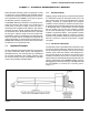
Chapter 1: Ultrasonic Measurement of Fasteners 1.1.3 Initial Pulse and Multi-Echo Measurement Modes The BoltMike III can be operated in one of two ultrasonic measurement modes: initial pulse (I.P.) and multi-echo (M.E.). In I.P. mode, as illustrated in Figure 1-2A, a sound pulse is sent through the fastener. The BoltMike’s triggering gate is positioned (based on the userinputted value of the fastener’s approximate length) to detect this sound pulse’s first returning echo.
Chapter 1: Ultrasonic Measurement of Fasteners wave to travel the length of the fastener two times. This duration is divided by two to find the time of flight (TOF), which represents the time it takes for the shock wave to travel once down the length of the fastener. The BoltMike then determines the ultrasonic length by first correcting the measured TOF for any changes in temperature, and then multiplying by the fastener’s acoustic velocity.
Chapter 1: Ultrasonic Measurement of Fasteners 1.1.6 Stress Stress occurs when load is applied to a fastener. When a tensile load (like the one shown in Figure 1-3) is applied to a fastener, the tensile stress is equal to the tensile load divided by the fastener’s average cross-sectional area (see the Appendix for average cross-sectional areas). The BoltMike calculates tensile stress in units of pounds per square inch (psi) or mega Pascal (MPa).
Chapter 1: Ultrasonic Measurement of Fasteners 1.1.9 Stress Factor (K) The velocity at which a longitudinal wave moves through an object is affected by stress. When a fastener is stretched there are two influences on its ultrasonic length (as determined by multiplying the sound wave’s time of flight by the constant value of acoustic velocity). First, the length of material through which the sound must travel increases. Also, the fastener’s actual acoustic velocity decreases as stress increases.
Chapter 1: Ultrasonic Measurement of Fasteners It is important to note that in order to change the acoustic velocity, stress must be applied in the same direction traveled by the ultrasonic shock wave. Thus shear and torsional stress have no effect on the acoustic velocity when measured along the fastener’s length. 1.1.10 Temperature Coefficient (Cp) The temperature of a fastener affects its physical length. As the temperature of a fastener increases, its physical length increases.
Chapter 1: Ultrasonic Measurement of Fasteners FIGURE 1-6—When the Calibration Group feature is used, known and measured loads for a group of fasteners are entered into the BoltMike. The correlation method chosen (vector or regression) determines if a stress ratio or a stress ratio and offset correction factor are then calculated. As you’ll learn in Chapter 6, the quantities inputted for fastener geometry have varying effects on the accuracy of the BoltMike’s calculations.
Chapter 1: Ultrasonic Measurement of Fasteners The BoltMike measures the time it takes for a sound wave to travel through a fastener. The sound wave, more specifically known as an ultrasonic shock wave or longitudinal wave, is created in the transducer. The wave is generated when a large electric pulse is sent to the transducer from the instrument. This pulse excites a piezoelectric element in the transducer. The wave’s frequency varies with the thickness of the piezoelectric element.
Chapter 1: Ultrasonic Measurement of Fasteners the stressed length is so small, little or no measurable elongation of the fastener occurs. In the same way, it is difficult to measure the effects of very low loads. Negligible elongation occurs when tensile stress levels are less than about 10% of the material’s ultimate tensile stress. The small errors in measurement introduced by removing and replacing the transducer (as described in section 2.
Chapter 1: Ultrasonic Measurement of Fasteners THIS PAGE WAS INTENTIONALLY LEFT BLANK.
Chapter 2: Fastener Preparation Chapter 2: Fastener Preparation Prior to measuring a fastener, it must be properly prepared for ultrasonic inspection. The fastener ends must be machined to be parallel and the end that will be mated with a transducer must be machined to a controlled, smooth surface finish. Further, to allow for proper coupling of the transducer and fastener, a suitable couplant must be applied.
Chapter 2: Fastener Preparation While the surface finish of the reflective surface is not as critical, very rough or uneven finish can produce errors. Use care when machining fastener ends. A common problem occurs when a small peak is left in the center of a fastener end after facing on a lathe. This small bump prevents the transducer from achieving proper contact and greatly reduces the signal amplitude.
Chapter 2: Fastener Preparation FIGURE 2-3—A consistent approach to transducer placement ensures accurate results.
Chapter 2: Fastener Preparation maximum-amplitude waveform may change. If the maximum-response location has changed, adjust the position of the transducer to the new location on the bolt head. This assures the optimum sound path is being used, both before and after tightening. Step 5: Position the transducer in the marked location (or at the newly identified maximum-amplitude location) to continue recording tensioned readings. 2.2.
Chapter 3: Transducer Selection Chapter 3: Transducer Selection A wide variety of ultrasonic transducers are available. Suitability for a specific application is determined based on the transducer’s center frequency, diameter, and damping. However, because there is often a broad range of applications for which transducers are suitable, and these ranges often overlap, it can be difficult to pick the “best” transducer for a specific job.
Chapter 3: Transducer Selection ducer cable length, affect the necessary amount of timedelay compensation. Repeat the transducer calibration whenever changing transducers or cables. As the probe’s contact surface wears with use, the instrument should be periodically rezeroed to compensate for any change in time delay. NOTE: When operating in multi-echo measurement mode, the transducer and instrument zero do not affect the instrument’s accuracy.
Chapter 4: Temperature Compensation Chapter 4: Temperature Compensation The temperature of a fastener affects its physical length. As the temperature of a fastener increases, its physical length increases. In addition, as a fastener’s temperature increases the amount of time it takes for sound to travel through the fastener also increases. In other words, when a fastener is subjected to increased temperature, its acoustic velocity decreases and, therefore, its ultrasonic length increases.
Chapter 4: Temperature Compensation more), the nonlinear thermal reaction becomes a factor and significant errors may occur. When temperature variations are relatively large and increased accuracy is desired, the temperature coefficient may be adjusted to the specific temperature range. 4.
Chapter 5: Selecting Phase Chapter 5: Selecting Phase When recording a reference (non-tensioned) fastener length, the operator must first select a measurement phase. This setting determines if the triggering gate is positioned above or below the A-scan zero level and, therefore, if the gate detects positive or negative heading portion of the signal. Once the measurement phase is selected, and an L-Ref is recorded, the phase may not be changed again for that fastener.
Chapter 5: Selecting Phase THIS PAGE WAS INTENTIONALLY LEFT BLANK.
Chapter 6: Fastener Geometry Chapter 6: Fastener Geometry As explained throughout Chapter 1 of this guide, many of the calculations made by the BoltMike rely directly on user-input fastener dimensions. A fastener’s material type, nominal length, average diameter, and effective length (also known as working or grip length) must be input in order for the BoltMike to perform all calculations.
Chapter 6: Fastener Geometry The effective length is calculated differently depending on the fastener application. The directions for calculating the effective length in four different cases are outlined in Figures 6-2 through 6-5. Note that the resulting values for effective length are approximate and may vary due to certain other factors. For example, consider an application using a bolt in a blind hole. Suppose the material strength of the bolt is greater than the threaded hole.
Chapter 6: Fastener Geometry FIGURE 6-4—This is typical of a configuration with a bolt (screw) turned into a threaded hole. When a headed fastener is threaded into a metal block, such as an automotive head bolt, calculate the effective length by adding half the diameter to one third the diameter (5/6 of the diameter total), then adding this amount to the clamp length. FIGURE 6-5—This is typical of a configuration with a stud turned into a threaded hole.
Chapter 6: Fastener Geometry 6.3 Fastener Cross-Sectional Area The cross-sectional area is the average area of that portion of a fastener that is subjected to tensile loading. In other words, it’s an average cross-sectional area taken over only the fastener’s effective length. The crosssectional area in threaded portions of the fastener should be calculated based on the thread’s minor diameter. The accuracy with which cross-sectional area is entered only affects the BoltMike load calculation.
Chapter 7: Material Constants Chapter 7: Material Constants As described in Chapter 1 of this guide, several constants are used by the BoltMike to represent the material properties of a specific fastener. You have the option of using constants already stored in the BoltMike for standard material types or defining constants for a custom material type. 7.
Chapter 7: Material Constants the CUSTOM material mode is activated, you edit the material name and any material property to match those of your non-standard material type. Even if you are able to obtain published constants for a non-standard material type, it is best to perform some amount of testing to determine the accuracy of the resulting measurements.
Chapter 8: BoltMike Formulas Chapter 8: BoltMike Formulas The BoltMike uses the following collection of formulas as a basis for all calculations and derived values. If using the formulas manually, be certain to convert all values to the units listed below, and to adhere to accepted rounding practices and number of significant digits. Finally, keep in mind that all BoltMike calculations are performed in metric units.
Chapter 8: BoltMike Formulas THIS PAGE WAS INTENTIONALLY LEFT BLANK.
Appendix: Tabular Data Appendix: Tabular Data NOTE: The tables contained in this appendix give the cross sectional stressed area for many standard sizes of bolt. The operator may choose to use these tables to determine the area of a fastener. IMPORTANT: These tables are provided for convenience only StressTel does not assume liability for errors. The BoltMike stores data in metric form.
Appendix: Tabular Data METRIC STANDARD THREAD Page 30 METRIC FINE THREAD Sizes mm Pitch mm Tensile Stress Area Sq. mm Sizes mm Pitch mm Tensile Stress Area Sq. mm M4 0.7 8.78 M8 1.0 39.2 M5 0.8 14.2 M9 1.0 51 M6 1.0 20.1 M 10 1.0 64.5 M7 1.0 28.9 M 10 1.25 61.2 M8 1.25 36.6 M 12 1.25 92.1 M 10 1.5 58.0 M 12 1.5 88.1 M 12 1.75 84.3 M 14 1.5 125 M 14 2.0 115 M 16 1.5 167 M 16 2.0 157 M 18 1.5 216 M 18 2.5 193 M 18 2.0 204 M 20 2.
Appendix: Tabular Data METRIC STANDARD THREAD WAIST BOLTS METRIC FINE THREAD WAIST BOLTS Sizes mm Pitch mm Waist Diameter mm Tensile Stress Area Sq. mm Sizes mm Pitch mm Waist Diameter mm Tensile Stress Area Sq. mm M4 0.7 2.83 6.28 M8 1.0 6.10 29.2 M5 0.8 3.62 10.3 M9 1.0 7.00 38.4 M6 1.0 4.30 14.5 M 10 1.0 7.90 49.0 M7 1.0 5.20 21.2 M 10 1.25 7.62 45.6 M8 1.25 5.82 26.6 M 12 1.25 9.42 69.7 M 10 1.5 7.34 42.4 M 12 1.5 9.14 65.7 M 12 1.75 8.87 61.
Appendix: Tabular Data FINE THREAD SERIES, UNF AND NF EXTRA FINE THREAD SERIES, UNEF AND NEF Sizes in. Basic Major Diameter in. Threads per in. Tensile Stress Area Sq. in. Sizes in. Basic Major Diameter in. Threads per in. Tensile Stress Area Sq. in. 12(.216) 0.2160 32 0.0270 0(.060) 0.0600 80 0.00180 1/4 0.2500 32 0.0379 1(.073) 0.0730 72 0.00278 5/16 0.3125 32 0.0625 2(.086) 0.0860 64 0.00394 3/8 0.3750 32 0.0932 3(.099) 0.990 56 0.00523 7/16 0.4375 28 0.
Appendix: Tabular Data COARSE THREAD SERIES, UNC AND NC 4-THREAD SERIES, 4UN Sizes in. Basic Major Diameter in. Threads per in. Tensile Stress Area Sq. in. 1(.073) 0.0730 64 0.000263 2(.086) 0.08660 56 0.00370 3(.099) 0.0990 48 0.00487 4(.112) 0.1120 40 0.00604 5(.125) 0.1250 40 0.00794 6(.138) 0.1380 32 0.00909 8(.164) 0.01640 32 0.0140 10(.190) 0.1900 24 0.0175 12(.216) 0.2160 24 0.0242 1/4 0.2500 20 0.0318 5/16 0.3125 18 0.0524 3/8 0.3750 16 0.
Appendix: Tabular Data 8-THREAD SERIES, 8UN 6-THREAD SERIES, 6UN Sizes Secondary Primary in. in. 1 3/8 1 7/16 1 1/2 1 9/16 1 5/8 1 11/16 1 3/4 1 13/16 1 7/8 1 15/16 2 2 1/8 2 1/4 2 3/8 2 1/2 2 5/8 2 3/4 2 7/8 3 3 1/8 3 1/4 3 3/8 3 1/2 3 5/8 3 3/4 3 7/8 4 4 1/8 4 1/4 4 3/8 4 1/2 4 5/8 4 3/4 4 7/8 5 5 1/8 5 1/4 5 3/8 5 1/2 5 5/8 5 3/4 5 7/8 6 Basic Major Diameter in. Tensile Stress Area Sq. in. 1.3750 1.4375 1.5000 1.5625 1.1555 1.2777 1.405 1.54 1.6250 1.6875 1.7500 1.8125 1.8750 1.68 1.83 1.98 2.
Appendix: Tabular Data 16-THREAD SERIES, 16UN 12-THREAD SERIES, 12UN Sizes Secondary Primary in. in. 9/16 5/8 11/16 3/4 13/16 7/8 15/16 1 1 1/16 1 1/8 1 3/16 1 1/4 1 5/16 1 3/8 1 7/16 1 1/2 1 9/16 1 5/8 1 11/16 1 3/4 1 13/16 1 7/8 1 15/16 2 2 1/8 2 1/4 2 3/8 2 1/2 2 5/8 2 3/4 2 7/8 3 3 1/8 3 1/4 3 3/8 3 1/2 3 5/8 3 3/4 3 7/8 4 4 1/8 4 1/4 4 3/8 4 1/2 4 5/8 4 3/4 4 7/8 5 5 1/8 5 1/4 5 3/8 5 1/2 5 5/8 5 3/4 5 7/8 6 Basic Major Diameter in. Tensile Stress Area Sq. in. 0.5625 0.182 0.6250 0.6875 0.7500 0.
Appendix: Tabular Data 20-THREAD SERIES, 20UN Sizes Secondary Primary in. in. 28-THREAD SERIES, 28UN Basic Major Diameter in. Tensile Stress Area Sq. in. 1/4 0.2500 0.0318 5/16 3/8 7/16 1/2 9/16 0.3125 0.3750 0.4375 0.5000 0.5625 0.0547 0.0836 0.1187 0.160 0.207 0.6250 0.6875 0.7500 0.261 0.320 0.386 13/16 0.8125 0.8750 15/16 Secondary in. Basic Major Diameter in. Tensile Stress Area Sq. in. 12(.216) 0.2160 0.0258 1/4 0.2500 0.0364 5/16 0.3125 0.0606 3/8 0.3750 0.0909 7/16 0.
Appendix: Tabular Data 32-THREAD SERIES, 32UN Sizes Primary in. Secondary in. Basic Major Diameter in. Tensile Stress Area Sq. in. 6(.138) 0.1380 0.00909 8(.164) 0.1640 0.0140 10(.190) 0.1900 0.0200 0.2160 0.0270 1/4 0.2500 0.0379 5/16 0.3125 0.0625 3/8 0.3750 0.0932 7/16 0.4375 0.1301 1/2 0.5000 0.173 9/16 0.5625 0.222 5/8 0.6250 0.278 0.6875 0.339 0.7500 0.407 0.8125 0.480 0.8750 0.560 0.9375 0.646 1.0000 0.738 12(.
Appendix: Tabular Data THIS PAGE WAS INTENTIONALLY LEFT BLANK.