Installation Instructions Built-In Wall Oven 27” (68.6 cm) models JCKS10, JCKP30, JCKP70, PCK916, PCK920 30” (76.2 cm) models JCTP30, JCTP70, PCT916, PCT920 If you have questions, call 1.800.561.3344 or visit our website at: www.geappliances.ca Before You Begin • Proper installation is the responsibility of the installer and product failure due to improper installation is NOT covered under warranty. • NOTE—This appliance must be properly grounded. Read these instructions carefully and completely.
Installation Instructions IMPORTANT SAFETY INSTRUCTIONS For Your Safety Electrical Requirements (cont.) • Be sure your oven is installed properly by a qualified installer or service technician. • Be sure the oven is securely installed in a cabinet that is firmly attached to the house structure. Weight on the oven door could cause the oven to tip and result in injury. Never allow anyone to climb, sit, stand or hang on the oven door.
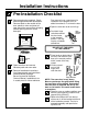
Installation Instructions Pre-Installation Checklist Door removal is not a requirement for installation of the product, but is an added convenience. To remove the door: Remove packaging materials. Check behind hinges and under false bottom. Remove labels on the outside of the door, plastic on trims and panel, all tape around the oven and any shipping screws securing the oven to the base pad. Open the oven door as far as it will go.
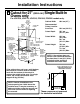
Installation Instructions A Cutout for 27″ (68.6 cm) Single Built-In Ovens only For JCKP30, JCKP70, JCKS10, PCK916, PCK920 models only. 12.7 cm (5”) Max. from the left or right Cabinet side Width 68.6 cm (27”) Allow 2.5 cm (1”) for overlap of oven over side edges of cutout Junction Box Location Cutout Width 63.5 cm (25”) Min. 64.1 cm (25 1/4”) Max. 55.9 cm (22”) Min. Cutout above base rail Height 70.2 cm (27 5/8”) Min. 71.4 cm (28 1/8”) Max.
Installation Instructions A Cutout for 30″ (76.2 cm) Single Built-In Ovens only For JCTP30, JCTP70, PCT916, PCT920 models only. Cutout Width 72.4 cm (28 1/2”) Min. 72.7 cm (28 5/8”) Max. 24.1 cm (9 1/2”) Max. Junction Box Location Allow 1.75 cm (11/16”) for overlap of oven over side edges of cutout Cabinet Width Recommended Cutout Location from Floor Cutout Depth Cutout Width Opening between inside walls must be at least 72.4 cm (28 1/2”) wide Cutout Height 69.2 cm (27 1/4”) Min. 69.
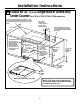
Installation Instructions A Cutout for 27″ (68.6 cm) Single Built-In Ovens only Under Counter For JCKP30, JCKP70, JCKS10, PCK916, PCK920 models only. Electric cooktops may be installed over this oven. See cooktop installation instructions for cutout size. See label on top of oven for approved cooktop models. 240V / 208V Junction Box Location (junction box may be in adjacent cabinet) 63.5 cm (25”) 19.7 cm (7 3/4”) Max.
Installation Instructions A Cutout for 30″ (76.2 cm) Single Built-In Ovens only Under Counter For JCTP30, JCTP70, PCT916, PCT920 models only. Gas or electric cooktops may be installed over this oven. See cooktop installation instructions for cutout size. See label on top of oven for approved cooktop models. 240V / 208V Junction Box Location (junction box may be in adjacent cabinet) 63.5 cm (25”) Top and/or side fillers may be necessary if unit is positioned between existing cabinets.
Installation Instructions A Cutout for 30″ (76.2 cm) Single Built-In Ovens only – Over a Warming Drawer For JCTP30, JCTP70, PCT916, PCT920 models only. Anti-Tip Block Against Rear Wall Per Warming Drawer Requirement 2” (5.1 cm) Min. Per Warming Drawer Requirement NOTE: Install the oven only with specific models listed on the label located on top of the oven. 1” (2.5 cm) Min.
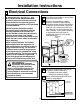
Installation Instructions B Electrical Connections ATTENTION INSTALLER B1 All electric wall ovens must be hard wired (direct wired) into an approved junction box. A plug and receptacle is NOT permitted on these products. B2 DO NOT shorten the flexible conduit. The conduit strain relief clamp must be securely attached to the junction box and the flexible conduit must be securely attached to the clamp.
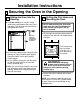
Installation Instructions C Securing the Oven in the Opening C1 Sliding the Oven Into the Opening C2 Drilling the Pilot Holes and Mounting the Oven a. Loop (do not tie) a 91 cm (36”) string around the conduit before the oven is slid into place. This will keep the conduit from falling behind the oven. NOTE: Before drilling the pilot holes, make sure the oven is pushed as far back into the opening as it will go and is centered. a.
Installation Instructions C3 Preparing for the Bottom Trim Installation C4 Installing the Metal Bottom Trim a. With oven installed, take the bottom trim and center it on the bottom front edge of the cabinet opening. a. Place the bottom metal trim centered over the pre-drilled mounting holes. Tape the edges of the trim down to maintain the alignment. b. Using the trim as a template, mark the center of each slot (two total) where the mounting holes will be drilled. c. Remove the trim. d.
Installation Instructions D Replacing the Oven Door NOTE: The oven door is heavy. You may need help lifting the door high enough to slide it into the hinge slots. Do not lift the door by the handle. D1 D3 Open the oven door as far as it will open. D4 Push the hinge locks up against the front frame of the oven cavity, to the locked position. Hinge in Locked Position Lift the oven door by placing one hand on each side. The door is heavy, so you may need help. Do not lift the door by the handle.
Installation Instructions Pre-Test Checklist Remove all protective film, if present, and any stickers. Check that the bottom trim is installed properly (see page 10). Check to be sure that all wiring is secure and not pinched or in contact with moving parts. Check to be sure the mounting screws are installed and flush with the side trim (see page 9). Operation Checklist Remove all items from the inside of the oven.
Notes 14
Notes 14
Directives d’installation Liste de vérification avant l’essai Vérifiez que les vis de montage sont bien en place et ne dépassent pas la surface de la garniture latérale (voir la page 9). Vérifiez que tout le câblage est bien fixé et qu’il n’est pas coincé ou en contact avec des pièces en mouvement. Vérifiez que la garniture inférieure est bien montée (voir la page 10). S’il y a lieu, enlevez la pellicule protectrice et les étiquettes collées sur le four.
D Directives d’installation Remise en place de la porte du four NOTE : La porte du four est lourde. II se peut que vous ayez besoin d’aide pour la soulever assez haut pour la glisser dans ses charnières. Ne soulevez pas la porte par la poignée. En maintenant la porte à la position d’enlèvement, qui correspond à peu près à la position fermée, placez l’encoche du bras de charnière dans le bord inférieur de la fente de la charnière. L’encoche doit être bien insérée dans le bas de la fente.
Directives d’installation a. Centrez la garniture inférieure métallique sur les trous de montage pré-perforés. Fixez les bords de la garniture avec du ruban adhésif pour en conserver l’alignement. a. Une fois le four installé, prenez la garniture inférieure et centrez-la sur le rebord inférieur frontal de l’ouverture de l’enceinte. C4 Installation de la garniture inférieure métallique C3 Préparation du montage de la garniture inférieure Pour les modèles b.
C Directives d’installation Fixation du four dans l’ouverture C1 Mise en place du four dans l’ouverture a. Faire passer (ne pas nouer) une ficelle de 91 cm (36 po) autour du conduit avant de faire glisser le four en place. On évitera ainsi de faire tomber le conduit en arrière du four. Tirez sur la ficelle tout en poussant le four dans l’enceinte b. Agrippez le four par l’intérieur de son orifice pour le soulever fermement jusque dans l’ouverture de l’enceinte.
B Directives d’installation Raccordement électrique B2 Tous les fours muraux encastrés doivent être raccordés (raccordement direct) dans une boîte de jonction approuvée. Une fiche et une prise de courant ne sont PAS autorisées pour brancher ce produit. B1 AVIS IMPORTANT À L’INSTALLATEUR : NE PAS raccourcir le conduit flexible. La bague anti-traction du conduit doit être fixée fermement à le boîte de jonction et le conduit flexible doit être fixé fermement à la bague.
A Directives d’installation Ouverture pour fours encastrés simples 30 po (76,2 cm) seulement – pour une installation au-dessus d’un tiroir chauffe-plat Pour les modèles JCTP30, JCTP70, PCT916, PCT920 seulement. Module antibasculement installé contre le mur arrière spécifications pour chaque tiroir chauffe-plat Dégagement min. : 5,1 cm (2 po) Spécifications pour chaque tiroir chauffe-plat NOTE : Installez le four uniquement avec les modèles précisés sur l’étiquette apposée sur le dessus du four.
A Directives d’installation Ouverture pour four encastré simple installé au dessous d’un comptoir 30 po (76,2 cm) Pour les modèles JCTP30, JCTP70, PCT916, PCT920 seulement. Une table de cuisson électrique ou au gaz peut être installée au-dessus de ce four. Voir les instructions d’installation de la table de cuisson pour connaître la taille de l’ouverture. Voir l’étiquette sur le dessus du four pour connaître les modèles de table de cuisson approuvés.
A Directives d’installation Ouverture pour four encastré simple installé au dessous d’un comptoir 27 po (68,6 cm) Pour les modèles JCKP30, JCKP70, JCKS10, PCK916, PCK920 seulement. Une table de cuisson électrique peut être installée au-dessus de ce four. Voir les instructions d’installation de la table de cuisson pour connaître la taille de l’ouverture. Voir l’étiquette sur le dessus du four pour connaître les modèles de table de cuisson approuvés.
A Directives d’installation Ouverture pour fours encastrés simples 30 po (76,2 cm) seulement Pour les modèles JCTP30, JCTP70, PCT916, PCT920 seulement. Largeur de l’ouverture 72,4 cm (28 1/2 po) min. 72,7 cm (28 5/8 po) max. 24,1 cm (9 1/2 po) max.
A Directives d’installation Ouverture pour fours encastrés simples 27 po (68,6 cm) seulement Pour les modèles JCKP30, JCKP70, JCKS10, PCK916, PCK920 seulement. 12,7 cm (5 po) max. à partir du côté Largeur de gauche ou droit l’enceinte 68,6 cm (27 po) Prévoir 2,5 cm (1 po) pour le chevauchement du four par-dessus les côtés de l’ouverture Emplacement de la boîte de jonction Largeur de l’ouverture 64,1 cm (25 po) min. 63,5 cm (25 1/4 po) max.
Directives d’installation Liste de vérification avant montage Enlevez tous les matériaux d’emballage. Vérifiez derrière les charnières et sous le faux fond. Enlevez les étiquettes sur la face extérieure de la porte, la matière plastique sur les garnitures et le panneau ainsi que le ruban collé autour du four. Enlevez aussi les vis d’expédition qui fixent le four sur sa base. II est possible d’enlever la porte du four pour faciliter l’installation, bien que cela ne soit pas obligatoire.
Directives d’installation CONSIGNES DE SÉCURITÉ IMPORTANTES La plaque signalétique est située sur la garniture latérale du four, sur le devant du cadre latéral ou sur le devant du cadre inférieur. • Assurez-vous que votre four est bien monté par un installateur qualifié ou un technicien de service. • Assurez-vous que votre four est monté en toute sécurité dans une enceinte qui est bien fixée à la structure de votre maison.
Directives d’installation Four mural encastré de modèles de 27 po (68,6 cm) JCKS10, JCKP30, JCKP70, PCK916, PCK920 modèles de 30 po (76,2 cm) JCTP30, JCTP70, PCT916, PCT920 Si vous avez des questions, composez le 1.800.561.3344 ou visitez notre site web à : www.electromenagersge.ca Avant de commencer Lisez complètement et attentivement les directives suivantes. • IMPORTANT—Conservez ces directives pour votre inspecteur local. • IMPORTANT—Respectez tous les codes et les décrets en vigueur.