Kalatel CBR-PB3-WD ProBridge Receipt Printer Interface Product Overview & Installation Manual
Warning! To prevent fire and electronic shock, do not expose this product to rain or moisture. The lightning flash with the arrowhead symbol, within an equilateral triangle, is intended to alert the user to the presence of uninsulated “dangerous voltage” within the products enclosure that may be of sufficient magnitude to constitute a risk of electric shock to persons.
Table of Contents 1 CBR-PB3-WD ProBridge.................................................. 5 1.1 1.2 1.3 1.4 2 Kalatel CBR-PB3-WD Description...................................................... 5 Additional Equipment Provided by the Installer................................... 5 Compatibility ..................................................................................... 5 Disclaimer......................................................................................... 5 Before You Begin .....
12 Cable Specifications.................................................... 33 13 Specifications .............................................................. 35 14 Warranty and Service .................................................. 36 14.1 14.2 Factory Service............................................................................... 36 Warranty.........................................................................................
1 CBR-PB3-WD ProBridge 1.1 Kalatel CBR-PB3-WD Description The Kalatel CBR-PB3-WD is a specific ProBridge unit for interfacing the DVMRe family of digital video multiplex/recorders Wayne Plus Receipt Printers (WP/RJ). One CBR-PB3-WD is required per cash register. Where multiple cash registers are connected to a single DVMRe unit, the individual CBR-PB3-WD’s are interconnected via the PB3’s built-in RS-485 network. 1.
2 Before You Begin 2.1 Installation Summary The basic steps to install the CBR-PB3-WD unit are: 1. Connect the PB3 to the Receipt Printer using the supplied cable. (If more than two PB3 units are used, verify that proper termination is set on each individual PB3 unit. 2. Connect the PB3 to the DVMRe-CT/eZT/StoreSafe unit using the supplied cable (RJ45-to-RJ45).
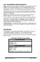
2.4 Installation Environment Power: Ensure that the installation site’s AC power is stable and within the rated voltage of the external power supply. If the site’s AC power is likely to have spikes or dips, use power line conditioning or an Uninterruptible Power Supply. Temperature: Observe the unit’s ambient temperature specifications when choosing a location for the unit. Extremes of heat or cold beyond the specified operating temperature limits may cause the unit to fail.
4310-0008 220VAC Power Supply Power Supply Input Voltage: 220 Volt AC Tolerance: ±10% Frequency: 50 Hz Power Supply Output Voltage: 12 Volt DC Current: 110mA Power: 1.3 Watts Connector: 2.1mm female barrel.
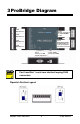
3 ProBridge Diagram SW1 Dipswitch 1-8 Port 1 RS232 Connection to Triplex/DVMRe or PC SW2 Dipswitch 1-8 SW3 Dipswitch 1-8 Port 0 RS485 Network Bus If multiple PB3s are connected together (use either connector) SW4 Dipswitch 1-8 Port 2 Connects to ECR and Receipt Printer NOTE Power Supply Connector 12VDC Port 0 and Port 1 each have identical looping RJ45 connectors.
Default (Factory) Dipswitch Settings SW1 SW2 SW3 SW4 1 Up 1 Down 1 Down 1 Up 2 Up 2 Down 2 Down 2 Up 3 Up 3 Down 3 Down 3 Down 4 Down 4 Down 4 Down 4 Up 5 Up 5 Down 5 Down 5 Up 6 Up 6 Down 6 Down 6 Up 7 Up 7 Down 7 Down 7 Down 8 Up 8 Down 8 Down 8 Up The default camera assignment is for the PB3’s transaction information to be associated with Camera 1.
4 Connection Diagram ECR Receipt Printer CBR-PB3-WD DB9M RJ45 (Port 0) DB9F ECR 4310-0034B Cable DB9F 4310-0078A Cable Receipt Printer CBR-PB3-WD DB9M RJ45 (Port 1) 4310-0034B Cable RJ45 (Port 0) DB9F 4310-0078A Cable DB9F DVMRe Triplex NOTE RS232 Port 2 If the distance between the nearest register PB3 is greater than 50’ (RS-232 distance limitation), an additional PB3 can be added near the DVMRe allowing RS-485 communication between the PB3 units.
Termination Switch Termination is set on SW4 for PORT 0 (Dipswitch #3) Termination is important whenever multiple PB3 units are interconnected via the unit’s built-in RS485 network. The default termination setting on the ProBridge 3 unit is with termination set to ON. Whenever there are more than two PB3’s, termination on some of the PB3 units will change.
5 Detailed Installation Steps 5.1 PB3 Physical Installation 1. Disconnect the existing Receipt Printer cable from the back of the POS system and install the ECR Interconnect Cable (4310-0078A) to the Receipt Printer as shown on page 11. 2. Reconnect the Receipt Printer Cable to one of the D9F connectors on the ECR Interconnect Cable as shown on page 11. 3. Connect the other end (DB9F) to the DB9M connector on the PB3 unit. 4. Connect the PB3 Power Supply to the unit.
5.2 Configuring the PB3 for POS Interface 1. Associating ECR data to a specific camera. Dipswitches 5-8 on SW1 are used for assigning an ECR’s transaction text to a specific camera. Please refer to Section 8 for the specific dipswitch camera assignments. The default setting is for switches 5-8 to be all OFF (All switches Up = Camera 1). 2. Program the DVMRe for the desired recording functions based upon the presence of transaction text.
iii. If the unit fails to display transaction text, please go to the troubleshooting section of this manual. b. To verify proper operation using a DVMRe–CS/CD/eZ, please refer to Section 11.
6 Special Functions NOTE If these settings are used, they must be turned off before normal transaction processing will resume. 6.1 Display Memory This setting displays all internal memory settings through Port 1 on the text box window of the selected camera on a DVMRe Triplex. This allows you to quickly check what settings are in your unit. To access this mode: SW1 1 Down 2 Down 3 Up 4 Up To exit this mode, return the dipswitches to the following position: SW1 1 Up 2 Up 3 Up 4 Up 6.
As a troubleshooting tool, this element allows you to verify that the PB3 is able to send messages and have the DVMRe correctly capture data coming from the PB3. In this mode, if text can be received and displayed, yet when attempting to process ECR data fails, then some other problem exists with respect to the ECR connection (cabling) or interface setup.
To exit this mode return the dipswitches to the following position: SW1 NOTE 1 Up 2 Up 3 Up 4 Up Power must be cycled OFF and then ON to the ProBridge unit before the reset command will take effect.
7 Troubleshooting If you are unable to verify capture of transaction text, do the following: 1. Check that each device is properly powered. 2. Check that the ECR to Camera address is correctly programmed SW1. 3. Check that all cables and cable connections are correct 4. If data is being displayed but is not intelligible, the likelihood is that the baud rate is different than the default value for the selected register. Check with the baud rate settings for the Receipt Printer on your POS system.
7. Section 4 contains all of the default Jumper Settings, if it is necessary for you to manually configure the interface. Troubleshooting Guide Problem Solution Red LED is not illuminated Check to make sure the power transformer is plugged in properly. Replace power transformer. Cannot display demo text Make sure the Triplex is showing the text box on Monitor A.
8 Text to Camera Address This section contains dipswitch settings for associating a specific Cash Register’s transaction text with a specific camera on the DVMRe unit. SW1 - Dipswitches 5-8 Dipswitches 5 thru 8 on SW1 assigns transaction text for that cash register’s PB3 unit to a specific camera on the DVMRe.
SW1 Dipswitch 5- 8 Camera Assignment Dipswitch Numbers Camera # 5 6 7 8 12 DOWN UP DOWN DOWN 13 DOWN DOWN UP UP 14 DOWN DOWN UP DOWN 15 DOWN DOWN DOWN UP 16 DOWN DOWN DOWN DOWN Kalatel CBR-PB3-WD 22 0150-0261A
9 Manual Switch Config Manual configuration should only be used if the “POS Device Selection” does not conform to your specific device because baud rates or protocols are slightly different than the default values for the selected device. 9.1 Manual Dipswitch Settings Available q Camera Address (SW1 – Dipswitches 5-8) – see Section 8 q Baud Rate (SW2 – Dipswitches 2-4) q Protocol (SW2 – Dipswitches 5-8) 9.1.
9.1.
SW2 Switch Setting q Protocol: Asynchronous q Parity: Even q Code: 8-Bit ASCII q Mode: 2 Stop Bit q Protocol: Asynchronous q Parity: Odd q Code: 8-Bit ASCII q Mode: 2 Stop Bit q Protocol: Asynchronous q Parity: None q Code: 8-Bit ASCII q Mode: 2 Stop Bit q Protocol: Asynchronous q Parity: Even q Code: 7-Bit ASCII q Mode: 2 Stop Bit q Protocol: Asynchronous q Parity: Odd q Code: 7-Bit ASCII q Mode: 2 Stop Bit q Protocol: Asynchronous q Parity: None q Code: 7-Bit
10 HyperTerminal Setup Manual configuration can also be completed using Windows HyperTerminal in lieu of the dipswitches. Manual configuration should only be used if the “POS Device Selection” does not conform to your specific device because baud rates or protocols are slightly different than the default values for the selected device. 10.1 Equipment Required q (1) Windows 98/NT/2000/XP Desktop or Laptop PC. q (1) DB9F to RJ45 cable (included with your unit).
10.2 Setting up the ProBridge for HyperTerminal Operation 1. Start HyperTerminal and open a new Connection (FILE>NEW): Give the connection a name and select an Icon. Click OK. 2. Under “Connect Using” option select “COM1”. 3. The Com1 Properties menu will appear. Select the following settings to complete the setup: 4. a. Bits per Second = 19200 b. Data Bits = 8 c. Parity = None d. Stop Bits = 1 e. Flow Control = None Power up the ProBridge unit by plugging in the power supply.
10.3 Manual HyperTerminal Configuration q The configurable settings are: o Protocol o Baud Rate o Parity o # of Stop Bits o Charcter Set o POS Device Type 1. The following screen (or similar) will confirm that you are in HyperTerminal programming mode. Initializing from DIP Switches Kalatel ProBridge III POS Ver: 2.10 Camera: 16 2. Once HyperTerminal mode is set up, press the “Enter” key twice. The following menu will appear: Main Menu 1. Exit 2. Port #2 3.
3. Setup Option 2 (Port #2) Port #2 is an RS-232 port that connects the PB3 unit to the Receipt Printer Interconnect Cable. The settings will vary based upon the type of Receipt Printer in use. Once you have selected this option, there will be multiple selections available for each element. Entering the number for the element will switch to the next option for that element. Continue to enter the same element number until the desired entry appears.
b. Menu Selection 3 – Baud Rate Baud Rate is only used if Protocol option selected is Asynchronous. q q q q q q q c. Menu Selection 4 – Parity q q q d. q 1-Stop (bit) 2-Stop (bit) Menu Selection 6 – Code (Character) The available selections are: q q f. None Odd Even Menu Selection 5 – Mode The available selections are: q e. 1200 2400 4800 9600 14.4K 19.2K 38.
11 PB3-POS with DVMRe -CD/CS Units If the unit to be connected to the PB3 is a DVMRe-CD (Duplex) or a DVMRe-CS (Simplex) unit, please note the following changes to the normal installation and configuration process below. Kalatel recommends using a DVMRe-CT (Triplex) unit to initially connect the PB3 unit to. The on-screen text display will make it easy to confirm successful capture of POS transactions.
gender changer is added to match the DB9M connector needed for the port on the DVMRe-CD/CS. ii. Modem must be configured for Port 1. The menu setup is: Communications>RS-232>Port 1> POTS. iii. The unit will have to be opened and a specific jumper setting set to allow text insertion on RS-232/2 Port. Contact Kalatel Tech Support for instructions on configuring the PORT 2 for text insertion.
12 Cable Specifications ProBridge to Triplex (DVMRe-CT) Part Number : 4310-0034B Communication Type: RS232 Pin 8: Pin 8: Pin 7: Common Pin 7: Common Connector Type: RJ-45, RJ-45 Cable Required: 5 Foot RJ-45 to RJ-45 Triplex RS232 Cable (Supplied). Connects ProBridge to DVMRe-CT.
ProBridge to ProBridge Cable Part Number : Installer Provided Communication Type: RS-485 Pin 8: Pin 8: Pin 7: Common Pin 7: Common Connector Type: RJ45, RJ45 Cable Required: RS-485 Interconnect Cable (up to 3,000’)). Interconnects multiple PB3’s in a RS485 network.
13 Specifications Physical Housing Metal enclosure. Dimensions (W x L x H) 4.0” x 7.0” x 1.0”. (100mm x 175mm x 25 mm) Nominal Weight 4.8 oz (136 g) Shipping Weight 1 lb (453 g) packaged, including the external AC power supply and manual. Color Black. Environmental Temperature 0 to 40 °C, operating. Relative Humidity 90%, non-condensing. Electrical AC Power External AC power supply included. Voltage Range: 110 to 240 VAC + 10% Current: 200 mA DC Power DC jack, positive center.
14 Warranty and Service 14.1 Factory Service If the unit requires factory service, contact the dealer who supplied the unit to you for the correct procedures on returning the unit to the factory or the nearest factory service center. If the dealer is not available, contact the manufacturer of the unit as detailed below and request a Return Material Authorization number (RMA). The unit’s serial number must be provided before an RMA number can be issued.
For all non-warranty repairs, the customer will be billed for parts, labor, and shipping. Labor will be billed in half-hour increments. Note: Customers requesting an estimate prior to repair will be notified by phone. If they cannot be reached, they will be notified by fax. If we are unable to reach the contact person for repair authorization after one phone attempt and two fax attempts, the equipment will be returned without being repaired. We will hold equipment no longer than two weeks.