
Installation guide


Installation Instructions
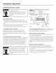
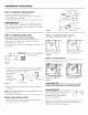
PREPARE HOT WATER LINE
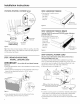
• The line may enter from either side, rear or floor within the
shaded area shown in Figure F.
• The line may pass through the same hole as the electrical
cable and drain hose. Or, cut an additional 1-1/2" diameter
hole to accommodate the water line. If power cord with plug
is used, water line must not pass through power cord hole.
/ I
/ I
I
(I 1-1/_" Dia.
Shut-off Hole
Valve
Ii
14
Hot ...... _
U .... "
\
I \
I \
I \
From
Cabinet
Cabinet Face
Figure F
2" From Floor
Water Line Connection
• Turn off the water supply.
• Install a hand shut-off valve in an accessible location, such
as under the sink. (Optional, but strongly recommended and
may be required by local codes.)
• Water connection is on the left side of the dishwasher. Install
the hot water inlet line, using no less than 3/8" copper tubing.
Route the line as shown in Figure F and extend forward at
least 19" from rear wall.
• Adjust water heater to deliver water at 120°F to 150°F at the
dishwasher.
• Flush water line to clean out debris.
• The hot water supply line pressure must be 20-120 PSI.
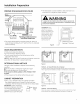
CAUTION:
Do not remove wood base until you are ready to install
the dishwasher. The dishwasher will tip over when the
door is opened if the wood base is removed.
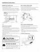
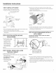
STEP i INSTALL TRIM PIECES
• Locate trim strips inside dishwasher.
• Presstrim onto the tub flange on each side. Start with the top
edge, pressing on as you move towards the bottom.
• Pressthe two top trim pieces on each side of the latch.
• Open and close the door to check that trim does not bind and
does not interfere with door latch.
Trim Strip
Trim -
Strip
Figure G
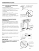
STEP 2 CHECK DOOR BALANCE
• With dishwasher on the wood skid, check the door balance
by opening and closing the door.
• If the door drops when released, increase the spring tension.
If the door rises when released, decrease the tension.
• Position the spring for increased or decreased tension as
required.
• Model families have different spring mounting holes and
tension adjustment methods. Refer to the appropriate figure
for your model.
PDW8200-PDW8900 Series
INCREASE
I)
DECREASE
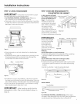
BEFORE YOU BEGIN
Locate the 2 Phillips special head countertop
bracket screws in the user bag. Set them aside
for use in Step 13. Remove drain hose from
upper rack, if it has not been pre-installed, and
set aside for use in Step 9.
Figure H