
Installation guide


Installation Instructions
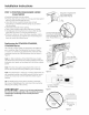
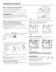
PDW9200-PDW9900, CDW9000 Series STEP 4 REMOVE TOEKICK
• Removethe 2 toekick screws
and toekick.
Set aside
for use in
Step 19.
Figure K
Remove 2
Toekick Screws
PulleL
Decrease
Tension
Shouldel
Correct Spring Increase
Cable Routing Tension
Figure I
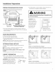
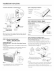
Tip: If door does not open easily or falls too quickly, check the
spring cable routing. Check that the cable is properly aligned
on the pulley. SeeFigure I,
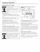
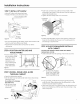
STEP 3 REMOVE WOOD BASE,
INSTALL LEVELING LEGS
IMPORTANT- Do not kick off wood base! Damage
will occur.
• Move the dishwasher close to the installation location and lay
it on its back.
• Remove the four leveling legs on the underside of the wood
base with an adjustable wrench or 15/16" socket.
• Discard base.
Figure J
• Screw leveling legs back into the dishwasher frame,
approximately 1/8" from frame as shown.
STEP 5 REMOVE TOEKICK BRACE
Only for PDW9700 series and PDW9900 series, otherwise
proceed to Step 6. t
• Removethe 2 toekick brace
screws (from the upper set of
mounting
holes) and
toekick brace.
Set aside
for use in
Step 19.
Figure L
Remove 2
Toekick Brace
Screws
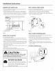
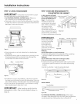
STEP 6 INSTALL POWER CORD
Skip this step if dishwasher will be direct wired or has a
factory installed power cord.
Use Power Cord Kit WXO9X70910, available for purchase
from on authorized GEAppliance Dealer.The power cord and
connections must comply with the National Electrical Code,
Section 422 and/or local codes and ordinances.
• Maximum power cord length is 6'.
A
Locate Insert Power
Junct,onBox Cord WiresThru _ _.\\_-_--1- )
Cover Wlth,n Strain Relief _ _"_ J
User Bag and Tighten _- v_
BCheckThatWhite,Blackand _
GreenDishwasherWiresAreThreaded _
Thru SmallHolein Bracket D ///
UseULListed
Figure M Wire Nuts
• Connect incoming power cord white (or ribbed) to dishwasher
white, black (or smooth) to black and ground to dishwasher
green wire. Use UL listed wire nuts of appropriate size.
• Installjunction box cover, Be sure wires are not pinched under
the cover,