Installation Instructions If you have questions, call 800.626.2000 or visit our website at: www.monogram.com Built-In Dishwashers ZBD6400, ZBD6500, ZBD6600 ZBD6700, ZBD6900, ZBD7000, ZBD7100 Chef’s Washers ZBD6605, ZBD6905, ZBD7005, ZBD7105 Design Guide with Installation Instructions Monogram. ® We bring good things to life.
Safety Information BEFORE YOU BEGIN • Read these instructions completely and carefully. • IMPORTANT - Save these instructions for local inspector’s use. Observe all governing codes and ordinances. • Note to Installer - Be sure to leave these instructions with the Consumer. • Note to Consumer - Keep these instructions with your Owner’s Manual for future reference. • If you received a damaged dishwasher, you should immediately contact your dealer or builder. READ CAREFULLY. KEEP THESE INSTRUCTIONS.
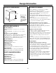
Design Information PRODUCT DIMENSIONS 34" Adjustable to 35" *24" 23-7/8" ADVANCE PLANNING • These dishwashers are designed for versatility, adaptable to virtually any installation. • All models have a full length door or a modified door to accept a full cabinet panel without the traditional access panel • Side tub flange trim is adjustable and will conceal any slight gap between the dishwasher and adjacent cabinetry.
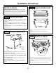
Installation Preparation MATERIALS YOU WILL NEED: Materials Required for All Installations Screw Type Clamps ¨ 90° Elbow (3/8”NPT external thread on one end, opposite end sized to fit water supply) Note: Use new ferrule. Do not use old parts.
Installation Preparation PARTS SUPPLIED: Remove the hardware accessory bag and other parts from inside or taped to the outside of the dishwasher. Check contents against illustrations to insure that all parts are included.
Installation Preparation DRAIN REQUIREMENTS Method 1 – Air Gap with Waste Tee or Disposer An air gap must be used when the waste tee or disposer connection is less than 18” from the floor. • Follow local codes and ordinances. • Do not exceed 10 feet distance to drain. • To prevent back flow into the dishwasher, connect drain line to an air gap or use a 30” high drain loop, depending on local codes.
Installation Preparation PREPARE ELECTRICAL WIRING FOR PERSONAL SAFETY: Remove house fuse or open circuit breaker before beginning installation. Do not use an extension cord or adapter plug with this appliance. Alternate Receptacle Location 18" 18" 6" AVERTISSEMENT POUR ASSURER LA SÉCURITÉ PERSONNELLE, il faut enlever le fusible ou couper le courant au disjoncteur avant de commencer l’installation. Avec cet appareil, il ne faut pas utiliser de rallonge ni d’adaptateur de prise.
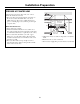
Installation Preparation PREPARE HOT WATER LINE The line may enter from either side, rear or floor within the shaded area shown. • The water line may pass through the same hole as the electrical cable and drain hose. Or, cut an additional 1-1/2" dia. hole to admit the line. If a power cord with plug is used, it must pass through a separate hole. Shut-off Valve 1-1/2" Dia. Hole Right Side Entry Approx. 40" from Wall 1-3/4" Hot Water Line Connection • Turn off the water supply.
Custom Panel Dimensions CUSTOM PANEL FOR MODELS ZBD6400 ONLY CUSTOM PANEL FOR MODELS ZBD7000 AND ZBD7005 Panel kits must be ordered separately. Installation of any custom panel should be completed before the dishwasher is installed. These models require a field installed 3/4" thick custom panel and custom handle. An installation template is packed with these models and may be obtained in advance. Order Pub. No. 49-5912. See page 15 for panel installation instructions.
Installation Instructions STEP 3 REMOVE ACCESS COVER BEFORE YOU BEGIN: CUSTOM PANEL INSTALLATION: If you intend to install custom door panels, (on some models) refer to trim kit installation instructions. Custom panels should be in place before installing the dishwasher. Insulation Board STEP 1 REMOVE PACKAGING Cut the shipping carton and use it as a pad beneath the dishwasher. This will protect the finished floor in the kitchen. • Remove wrapping and uncoil the drain hose in the back of the dishwasher.
Installation Instructions STEP 5 INSTALL POWER CORD STEP 7 SLIDE DISHWASHER INTO OPENING SKIP THIS STEP IF DISHWASHER WILL BE DIRECT WIRED DO NOT PUSH AGAINST THE FRONT PANEL WITH KNEES, DAMAGE WILL OCCUR! • Insert drain hose into the cabinet wall hole. If a power cord is used, guide the end through a separate hole. • Maximum power cord length is 6 ft. • The power cord and connections must comply with the National Electrical Code, Section 422 and/or local codes and ordinances.
Installation Instructions STEP 9 CONNECT DRAIN LINE STEP 10 CONNECT ELECTRICAL FOLLOW ALL LOCAL CODES AND ORDINANCES. FOR DIRECT WIRE ONLY (If a power cord with plug is used, plug it into the wall outlet and continue with next step.) • The dishwasher is supplied with a 72" long drain hose. • If a longer drain hose is required, add up to 48” of length for a total of 10 ft. length. • Secure the drain hose to the air gap, waste tee or disposer with clamps. • Make sure drain hose is not kinked.
Installation Instructions STEP 11 POSITION AND LEVEL THE DISHWASHER • Check to be sure the dishwasher is adjusted to correct height and is centered in the cutout. • Open and close the door to insure proper operation of the door. If there is any binding or rubbing, readjust leveling legs. Door Rub Door Rub On Right On Left Hand Side Hand Side CRE NS W NS U U Use a wrench to make adjustments.
Installation Instructions STEP 14 SECURE DISHWASHER TO CABINET AND COUNTERTOP STEP 15 INSTALL TOEKICK • Loosen depth adjustment screws inside the bracket. • Slide bracket out to proper depth. Tighten screws. • Attach supplied toekick to brackets with screws C provided. Do not tighten. • Adjust the toekick to touch the floor. Tighten screws. To maintain position and alignment, the dishwasher must be secured to the countertop and adjacent cabinets.
Panel Installation for Models ZBD7000 and ZBD7005 The custom panel should be prepared by your cabinet manufacturer according to the instructions shown on page 9. Use the supplied installation template to locate the mounting screws for the door. STEP 4 INSTALL CUSTOM HANDLE Screws Must Be Countersunk Into Panel STEP 1 DRAW CENTERLINE 4-1/2" Max. From Top of Panel Handle Custom Door Panel • Place the custom panel on a flat surface with appearance side down.
Note: While performing installations described in this book, safety glasses or goggles should be worn. TM For Monogram local service in your area, call 1-800-444-1845. Note: Product improvement is a continuing endeavor at General Electric. Therefore, materials, appearance and specifications are subject to change without notice. ® Monogram. General Electric Company Louisville, KY 40225 0616 400 327 Pub. No. 49-5905-2 Dwg. No. 165D4700P231 (N.D.