Installation Instructions Over the Range Microwave Oven Questions? Call 800.GE.CARES (800.432.2737) or Visit our Website at: Hotpoint.com BEFORE YOU BEGIN Read these instructions completely and carefully. • IMPORTANT – Save these instructions for local inspector’s use. • IMPORTANT – Observe all • Note to Installer – Be sure to leave these governing codes and ordinances. Note to Consumer – Keep these instructions for future reference.
Installation Instructions C CONTENTS Recirculating ........................................ 19–22 Attach Mounting Plate to Wall ............19 General information Preparation of Top Cabinet ................19 Important Safety Instructions .................................. 3 Electrical Requirements .......................................... 3 Adapting Microwave Blower for Recirculation ..........................20, 21 Hood Exhaust ......................................................
Installation Instructions IMPORTANT SAFETY INSTRUCTIONS You should have the wall receptacle and circuit checked by a qualified electrician to make sure the receptacle is properly grounded. This product requires a three-prong grounded outlet. The installer must perform a ground continuity check on the power outlet box before beginning the installation to insure that the outlet box is properly grounded.
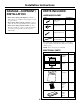
Installation Instructions HOOD EXHAUST NOTE: Read these next two pages only if you plan to vent your exhaust to the outside. If you plan to recirculate the air back into the room, proceed to page 6. OUTSIDE TOP EXHAUST (EXAMPLE ONLY) The following chart describes an example of one possible ductwork installation. EQUIVALENT LENGTH x NUMBER USED = EQUIVALENT LENGTH Roof Cap 24 Ft. x (1) = 24 Ft. 12 Ft. Straight Duct (6″ Round) 12 Ft. x (1) = 12 Ft.
Installation Instructions Maximum duct length: NOTE: If you need to install ducts, note that the total duct length of 31⁄4″ x 10″ rectangular or 6″ diameter round duct should not exceed 140 equivalent feet. Outside ventilation requires a HOOD EXHAUST DUCT. Read the following carefully. NOTE: It is important that venting be installed using the most direct route and with as few elbows as possible. This ensures clear venting of exhaust and helps prevent blockages.
Installation Instructions PARTS INCLUDED DAMAGE—SHIPMENT/ INSTALLATION HARDWARE PACKET • If the unit is damaged in shipment, return the PART unit to the store in which it was bought for repair or replacement. • If the unit is damaged by the customer, repair or replacement is the responsibility of the customer. • If the unit is damaged by the installer (if other than the customer), repair or replacement must be made by arrangement between customer and installer.
Installation Instructions TOOLS YOU WILL NEED # 1 and #2 Phillips screwdriver Tin snips (for cutting damper, if required) Ruler or tape measure and straight edge Pencil Scissors (to cut template, if necessary) Electric drill with 3⁄16″, 1⁄2″ and 5⁄8″ drill bits Carpenter square (optional) Filler blocks or scrap wood pieces, if needed for top cabinet spacing (used on recessed bottom cabinet installations only) Gloves Saw (saber, hole or keyhole) Stud finder or Safety goggles Level Hammer (optiona
Installation Instructions 1 PLACEMENT OF THE MOUNTING PLATE A. REMOVING THE MICROWAVE OVEN FROM THE CARTON/ REMOVING THE MOUNTING PLATE B. FINDING THE WALL STUDS 1 Remove the installation instructions, filter, glass tray, the exhaust adaptor and the small hardware bag. Do not remove the Styrofoam protecting the front of the oven. Wall Studs 2 Fold back all 4 carton flaps fully against carton sides. Then carefully roll the oven and carton over onto the top side.
Installation Instructions C. DETERMINING WALL PLATE LOCATION UNDER YOUR CABINET Template beneath cabinet with recessed bottom Template beneath cabinet with flat bottom Trim the rear wall template along the dotted line. 16-1/2″ CL Trim the rear wall template along the dotted line. Draw a vertical line on the wall at the center of the 30″ to 36″ wide space. Tape the Rear Wall Template onto the wall matching the centerline and touching the bottom of the cabinet.
Installation Instructions D. DETERMINING REAR MOUNTING SCREW LOCATIONS CL CAUTION: Wear gloves to avoid cutting fingers on sharp edges. NOTE: The Rear Wall Template serves to position the bottom mounting plate and to locate the horizontal exhaust outlet. 1 Use a level to check that the template is positioned accurately. 2 Locate and mark at least one stud on the left or right side of the centerline.
Installation Instructions 2 INSTALLATION TYPES (Choose A, B or C) This microwave oven is designed for adaptation to the following three types of ventilation: A. Outside Top Exhaust (Vertical Duct) B. Outside Back Exhaust (Horizontal Duct) C. Recirculating (Non-Vented Ductless) A NOTE: This microwave is shipped assembled for Outside Top Exhaust (except for non-vented models). Select the type of ventilation required for your installation and proceed to that section.
Installation Instructions A OUTSIDE TOP EXHAUST (Vertical Duct) INSTALLATION OVERVIEW A1. Attach Mounting Plate to Wall A2. Prepare Top Cabinet A3. Check Damper Operation A4. Mount Microwave Oven A5. Adjust Exhaust Adaptor A6. Connect Ductwork To use toggle bolts: A1.
Installation Instructions A3. INSTALL THE DAMPER (cont.) A2. USE TOP CABINET TEMPLATE FOR PREPARATION OF TOP CABINET Damper The top cabinet template will help you locate the top support screw holes, power cord and exhaust outlet locations. Reinstall rear retaining screw • Close the blower cover with adaptor and reinstall rear screw. • Remove tape holding the damper. The damper should pivot easily.
Installation Instructions A5. ADJUST THE EXHAUST ADAPTOR A4. MOUNT THE MICROWAVE OVEN (cont.) 3 Insert a self-aligning screw through top center cabinet hole. Temporarily secure the oven by turning the screw at least two full turns after the threads have engaged. (It will be completely tightened later.) Be sure to keep power cord tight. Be careful not to pinch the cord, especially when mounting flush to bottom of cabinet. Open the top cabinet and adjust the exhaust adaptor to connect to the house duct.
Installation Instructions B OUTSIDE BACK EXHAUST (Horizontal Duct) INSTALLATION OVERVIEW B1. Prepare Rear Wall B2. Remove Exhaust Adaptor B3. Attach Mounting Plate to Wall B4. Prepare Top Cabinet B5. Adapt Blower for Back Exhaust B6. Mount the Microwave Oven B1. PREPARING THE REAR WALL FOR OUTSIDE BACK EXHAUST The rear wall template should be positioned accurately as shown on page 9. • Read the instructions on the REAR WALL TEMPLATE.
Installation Instructions B2. ATTACH THE MOUNTING PLATE TO THE WALL B3. USE TOP CABINET TEMPLATE FOR PREPARATION OF TOP CABINET The top cabinet template will help you locate the top support screw holes and power cord cutout. Remove the template from the rear wall. The mounting plate must be secured to the wall using at least 3 toggle bolts and one wood screw. The wood screw must engage a wall stud. 1 Remove the toggle wings from the bolts.
Installation Instructions 6 Tilt and place the blower unit back into the opening in the top of the microwave. B4. ADAPTING MICROWAVE BLOWER FOR OUTSIDE BACK EXHAUST (cont.) 3 Carefully slide the blower motor toward the right, and lift it partially out of the opening. Note: The blower wires are long enough to allow flexible handling while performing these steps. Disconnect the wires only if it is necessary for additional flexibility. CAUTION: Do not pull or stretch the blower unit wiring.
Installation Instructions Cabinet Front B6. MOUNT THE MICROWAVE OVEN Cabinet Bottom Shelf Filler Block Equivalent to Depth of Cabinet Recess Self-Aligning Screw FOR EASIER INSTALLATION AND PERSONAL SAFETY, WE RECOMMEND THAT TWO PEOPLE INSTALL THIS MICROWAVE OVEN. NOTE: If your cabinet is metal, use the nylon grommet around the power cord hole to prevent cutting of the cord. NOTE: We recommend using filler blocks if the cabinet front hangs below the cabinet bottom shelf.
Installation Instructions C RECIRCULATING (Non-Vented Ductless) INSTALLATION OVERVIEW C1. Attach Mounting Plate to Wall C2. Prepare Top Cabinet C3. Check Microwave Assembly C4. Adapt Blower for Recirculation C5. Mount the Microwave Oven C6. Install Charcoal Filter 3 Place the mounting plate against the wall and insert the toggle wings into the holes in the wall to mount the plate.
Installation Instructions 3 Carefully slide the blower motor toward the right, and lift it partially out of the opening. Note: The blower wires are long enough to allow flexible handling while performing these steps. Disconnect the wires only if it is necessary for additional flexibility. C3. ADAPTING MICROWAVE BLOWER FOR RECIRCULATION 1 Remove the back top center blower motor door retaining screw.
Installation Instructions NOTE: When mounting the microwave oven, thread power cord through hole in bottom of top cabinet. Keep it tight throughout Steps 1–3. Do not pinch cord or lift oven by pulling cord. C3. ADAPTING MICROWAVE BLOWER FOR RECIRCULATION (cont.) 6 Tilt and place the blower unit back into the opening in the top of the microwave. CAUTION: Do not pull or stretch the blower unit wiring. Make sure the wires are not pinched.
Installation Instructions C4. MOUNT THE MICROWAVE OVEN (cont.) C5. INSTALLING THE CHARCOAL FILTER ACCESSORY 1 Remove the 3 screws along the top front edge of the oven using a #1 Phillips screwdriver. 2 Open the door. 3 Remove the grille by sliding it to the left and then pulling it straight off. 4 Insert 2 self-aligning screws through outer top cabinet holes. Turn two full turns on each screw. Charcoal Filter 5 Tighten center screw completely. 4 Install the charcoal filter.
Installation Instructions BEFORE YOU USE YOUR MICROWAVE 1. Make sure the microwave oven has been installed according to instructions. 2. Remove all packing material from the microwave oven. 3. Install turntable and ring in cavity. 4. Replace house fuse or turn breaker back on. 5. Plug power cord into a dedicated 15- to 20-amp electrical outlet. Ensure proper ground exists before use 23 6. Read the Owner’s Manual. 7. KEEP INSTALLATION INSTRUCTIONS FOR THE LOCAL INSPECTOR’S USE.
39-40425 Printed in Malaysia 10-04 JR DE68-02957A
Instrucciones de instalación Horno microondas para colocar encima de la estufa ¿Preguntas? Llame 800.GE.CARES (800.432.2737) o visite nuestra página en la red en: Hotpoint.com ANTES DE EMPEZAR Lea estas instrucciones completa y cuidadosamente. • IMPORTANTE – Guarde estas instrucciones para el uso del inspector local. • IMPORTANTE – Cumpla con todos los códigos y ordenanzas gubernamentales. • Nota para el instalador – Asegúrese de dejar estas instrucciones con el consumidor.
Instrucciones de instalación C CONTENIDO Recirculación ........................................ 19–22 Información general Cómo adherir el plato de montaje a la pared ............................................19 Instrucciones de seguridad importantes .................. 3 Cómo preparar el gabinete superior ....19 Requisitos eléctricos ................................................ 3 Cómo adaptar el ventilador del microondas para la recirculación....20, 21 Campana de escape........................
Instrucciones de instalación INSTRUCCIONES DE SEGURIDAD IMPORTANTES Deberá hacer que un técnico calificado inspeccione el tomacorriente de pared y el circuito para asegurarse de que el tomacorriente esté conectado a tierra de manera apropiada. Este producto requiere un tomacorriente eléctrico de tres patas conectado a tierra.
Instrucciones de instalación CAMPANA DE ESCAPE NOTA: Lea las siguientes dos páginas solamente si planea ventilar el escape hacia el exterior. Si por el contrario planea recircular el aire de vuelta hacia el salón, continúe en la página 6. ESCAPE SUPERIOR EXTERNO (EJEMPLO SOLAMENTE) La siguiente tabla describe un ejemplo de una posible instalación de red de conductos.
Instrucciones de instalación Longitud máxima del conducto: NOTA: Si usted necesita instalar conductos, tenga pendiente que la longitud total del conducto rectangular de 31⁄4″ x 10″ o el conducto redondo de 6″ de diámetro no debe sobrepasar 140 pies equivalentes. La ventilación externa requiere un CONDUCTO DE CAMPANA DE ESCAPE. Lea lo siguiente cuidadosamente. NOTA: Es importante que la ventilación sea instalada usando la ruta más directa y con la menor cantidad de codos posible.
Instrucciones de instalación PARTES INCLUIDAS DAÑOS— ENVÍO/INSTALACIÓN PAQUETE DE ELEMENTOS • Si la unidad se daña durante el envío, devuelva PARTE la unidad al almacén donde la adquirió para su reparación o reemplazo. • Si el cliente daña la unidad, la reparación o el reemplazo es responsabilidad del cliente. • Si el instalador daña la unidad (si no es el cliente), la reparación o reemplazo se debe hacer por medio de un arreglo entre el cliente y el instalador.
Instrucciones de instalación HERRAMIENTAS QUE NECESITARÁ Regla recta y cinta métrica Destornilladores de estrella #1y#2 Tijeras para cortar latón (para cortar el regulador de tiro, si es necesario) Lápiz Escuadra de carpintero (opcional) Tijeras (para cortar la plantilla, si es necesario) Taladro eléctrico con brocas de ⁄ ″, 1⁄2″ y 5⁄8″ 3 16 Guantes Bloques de relleno o pedazos de madera, si son necesarios para rellenar el gabinete (usados solamente en la instalación de gabinetes apoyados) Detector
Instrucciones de instalación 1 CÓMO COLOCAR EL PLATO DE MONTAJE A. CÓMO REMOVER EL HORNO MICROONDAS DEL EMBALAJE/ CÓMO REMOVER EL PLATO DE MONTAJE B. CÓMO ENCONTRAR LOS POSTES DE VIGA EN LA PARED 1 Remueva las instrucciones de instalación, el filtro, la bandeja de cristal y la bolsa pequeña del equipo. No remueva el protector frontal de espuma de poliestireno del horno. Postes de viga en la pared 2 Doble totalmente hacia atrás las cuatro tapas de cartón hacia los lados opuestos de la caja.
Instrucciones de instalación C. CÓMO DETERMINAR LA LOCALIZACIÓN DEL PLATO DE MONTAJE DEBAJO DE SU GABINETE Plantilla debajo de gabinete con fondo empotrado Plantilla debajo de gabinete de fondo plano Recorte la plantilla de la pared posterior a lo largo de la línea punteada. 16-1/2″ CL Recorte la plantilla de la pared posterior a lo largo de la línea punteada. Trace una línea vertical en la pared en el centro del espacio de 30″ a 36″ de ancho.
Instrucciones de instalación D. CÓMO DETERMINAR LA LOCALIZACIÓN DE LOS TORNILLOS TRASEROS DE MONTAJE CL PRECAUCIÓN: Use guantes de protección para evitar cortaduras en sus dedos con los extremos filosos. NOTA: La plantilla de la pared posterior sirve para colocar el plato de montaje inferior y localizar la salida del escape horizontal. 1 Use un nivel para verificar que la plantilla está colocada correctamente.
Instrucciones de instalación 2 TIPOS DE INSTALACIÓN Este horno microondas está diseñado para adaptarse a los siguientes tres tipos de ventilación: A. Escape superior exterior (Conducto vertical) B. Escape posterior exterior (Conducto horizontal) C. Recirculación (Sin conducto de ventilación) A (Escoja A, B o C) NOTA: Este horno microondas es enviado ya ensamblado para un escape superior exterior (excepto para modelos sin ventilación).
Instrucciones de instalación A ESCAPE SUPERIOR EXTERIOR (Conducto vertical) PERSPECTIVA GENERAL DE LA INSTALACIÓN A1. Cómo adherir el plato de montaje a la pared A2. Prepare el gabinete superior A3. Inspeccione la operación del regulador de tiro. A4. Monte el horno microondas A5. Ajuste el adaptador de escape A6. Conecte el conducto Para usar los tornillos basculantes: A1.
Instrucciones de instalación A3. INSTALE EL REGULADOR Reinstale el tornillo DE TIRO (cont.) A2. USE LA PLANTILLA DEL GABINETE SUPERIOR PARA LA PREPARACIÓN DEL GABINETE SUPERIOR retenedor posterior • Cierre la tapa del La plantilla del gabinete superior le ayudará a localizar los orificios de los tornillos para el soporte superior, el cable eléctrico y los puntos de salida del escape. • • Regulador ventilador con el adaptador y vuelva a instalar el tornillo posterior.
Instrucciones de instalación A5. CÓMO AJUSTAR EL ADAPTADOR DE ESCAPE A4. CÓMO MONTAR EL HORNO MICROONDAS (cont.) Abra el gabinete superior y ajuste el adaptador de escape para conectarlo al conducto de la casa. 3 Inserte un tornillo de autoalineación a través del agujero central superior del gabinete. Asegure el horno temporalmente girando el tornillo por lo menos dos vueltas completas después de que las roscas hayan agarrado. (Luego quedarán totalmente apretadas).
Instrucciones de instalación B ESCAPE POSTERIOR EXTERIOR PERSPECTIVA GENERAL DE LA INSTALACIÓN B1. Prepare la pared posterior B2. Remueva el adaptador de escape B3. Pegue el plato de montaje a la pared B4. Prepare el gabinete superior B5. Adapte el ventilador para escape posterior exterior B6. Monte el horno microondas B1. CÓMO PREPARAR LA PARED POSTERIOR PARA EL ESCAPE POSTERIOR La plantilla para la pared posterior debe ser colocada tal como se muestra en la página 9.
Instrucciones de instalación B2. CÓMO ADHERIR EL PLATO DE MONTAJE A LA PARED B3. USE LA PLANTILLA DEL GABINETE SUPERIOR PARA PREPARAR EL GABINETE SUPERIOR La plantilla del gabinete superior le ayudará a localizar los orificios de los tornillos para el soporte superior y el corte para el cable eléctrico. Retire la plantilla de la pared posterior. El plato de montaje se debe asegurar a la pared usando como mínimo 3 tornillos basculantes y un tornillo de madera.
Instrucciones de instalación 6 Incline y coloque la unidad del ventilador de nuevo en la abertura en la parte superior del microondas. B4. CÓMO ADAPTAR EL VENTILADOR DEL MICROONDAS PARA EL ESCAPE POSTERIOR EXTERIOR (cont.) 3 Con cuidado deslice el motor del ventilador hacia la derecha, y levántelo parcialmente hacia fuera de la abertura. Nota: Los cables del ventilador tienen suficiente longitud para permitir un manejo flexible mientras realiza estos pasos.
Instrucciones de instalación Frente del gabinete B6. CÓMO MONTAR EL HORNO MICROONDAS Estante del fondo del gabinete Bloque de relleno Equivalente a la profundidad del retroceso del gabinete Tornillo autoalineable PARA OBTENER UNA INSTALACIÓN MÁS FÁCIL Y EN POS DE LA SEGURIDAD PERSONAL, SE RECOMIENDA QUE DOS PERSONAS INSTALEN ESTE HORNO MICROONDAS. NOTA: Si su gabinete es de metal, use la arandela de nilón alrededor del cable eléctrico para evitar que el mismo sea cortado.
Instrucciones de instalación C RECIRCULACIÓN (Sin conducto de ventilación) PERSPECTIVA GENERAL DE LA INSTALACIÓN C1. Pegue el plato de montaje a la pared C2. Prepare el gabinete superior C3. Inspeccione la ensambladura del microondas C4. Adapte el ventilador para recirculación C5. Monte el horno microondas C6. Instale el filtro de carbonilla 3 Coloque el plato de montaje contra la pared e inserte las alas de mariposa en los agujeros de la pared para montar el plato.
Instrucciones de instalación 3 Con cuidado deslice el motor del ventilador hacia la derecha, y levántelo parcialmente hacia fuera de la abertura. Nota: Los cables del ventilador tienen suficiente longitud para permitir un manejo flexible mientras realiza estos pasos. Desconecte los cables únicamente si es necesario para flexibilidad adicional. C3.
Instrucciones de instalación C3. CÓMO ADAPTAR EL VENTILADOR DEL MICROONDAS PARA LA RECIRCULACIÓN (cont.) NOTA: Cuando se encuentre montando el horno microondas, enrosque el cable eléctrico a través del agujero en el fondo del 1 Levante el horno gabinete superior. Manténgalo microondas, inclínelo tenso a través de los Pasos del 1-3. hacia adelante y No pellizque el cable ni tire del enganche las ranuras horno por el cable. en el extremo inferior posterior en cuatro orejillas inferiores del plato de montaje.
Instrucciones de instalación C4. CÓMO MONTAR EL HORNO MICROONDAS (cont.) C5. CÓMO INSTALAR EL FILTRO DE CARBONILLA 1 Remueva los 3 tornillos del borde superior frontal usando un destornillador de estrella #1. 2 Abra la puerta. 3 Remueva la rejilla deslizándola hacia la izquierda y luego halándola hacia fuera. 4 Inserte 2 tornillos autoalineables a través de los agujeros exteriores superiores del horno. Gire dos vueltas completas en cada tornillo.
Instrucciones de instalación ANTES DE COMENZAR A USAR SU HORNO MICROONDAS 1. Cerciórese de que el horno ha sido instalado de acuerdo con las instrucciones. 5. Enchufe el cable eléctrico en un tomacorriente exclusivo de 15 a 20 amperios. Cerciórese de que existe una conexión a tierra apropiada 2. Remueva todos los materiales de embalaje del horno microondas. 3. Instale el aro rotatorio y con ruedas en la cavidad. 4. Reemplace el fusible de la casa o encienda de nuevo el interruptor. 23 6.
39-40425 Impreso en Malasia 10-04 JR DE68-02957A