
Installation Guide
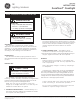

GEH-5942
INSTRUCTIONS
Decaflood
®
Floodlight
READ THOROUGHLY BEFORE INSTALLING
GENERAL
This luminaire is designed for outdoor lighting
applications, and should not be used in areas of limited
ventilation, or in high ambient temperature enclosures.
Best results will be obtained if installed and maintained
according to the following recommendations.
UNPACKING
This luminaire has been properly packed so that no
parts should have been damaged during transit. Inspect to
confirm.
MOUNTING
CAUTION
Unit will fall if not installed properly
• Follow installation instructions
WARNING
Risk of electric shock
• Turn power off before servicing
– see instructions
WARNING
Risk of fire
• Keep combustible materials away
from lens – see instructions
• Use lamps specified on nameplate
This floodlight is provided with either trunnion
mounting, or tenon mounting. Luminaires are supplied with
a tamper resistant screw that should be used to secure the
door for low or ground mounted applications.
NOTE: The unit may be mounted to point from
straight up to straight down but in no case may the
ballast be located above the optical.
1. TRUNNION MOUNTED UNITS — Mounted directly on a
flat surface. Mounting adapters are available for installa-
tion on poles, cross-arms, pipes, etc.
The trunnion bracket has a clearance hole for a 3/4-inch
bolt used for attachment to such mountings. The 3/8-inch
holes on either side permit additional anchoring, where
required. Tighten side trunnion bolts to 50 -55 foot
pounds.
2. TENON MOUNTED UNITS — The slipfitter can be
mounted on 1-7/8-inch O.D. through 2-3/8-inch O.D.
Three set screws are used to clamp the floodlight securely to
the pipe. Tighten set screws to 18 -22 foot pounds.
WIRING
Make all electrical connections in accordance with
the National Electrical Code and any applicable local
code requirements.
Verify that supply voltage is correct by comparing it
to nameplate.
Luminaires are supplied with multi-volt (120/208/240/
277 volts) ballasts. If another voltage is designed, remove
wire crimp from ballast and input voltage leads and recon-
nect input voltage lead to ballast lead marked with desired
voltage. Be sure to insulate the previously used ballast lead
with wire nut or other appropriate means.
Connect ground lead to the green lead, green ground
screw on housing or terminal block provided.
Do not remove insulated connectors from wires not
needed for required voltage connection.
These instructions do not purport to cover all details or variations in equipment nor to provide for every possible contingency to be met in connection with installation, operation or
maintenance. Should further information be desired or should particular problems arise which are not covered sufficiently for the purchaser’s purposes, the matter should be referred
to GE Lighting Solutions.
g
GE
Lighting Solutions