E4H SERIES WATER PURIFICATION MACHINES OPERATION AND MAINTENANCE MANUAL
OPERATION AND MAINTENANCE MANUAL FOR GE OSMONICS E4H SERIES WATER PURIFICATION MACHINES TABLE OF CONTENTS Page 1.0 DESCRIPTION ......................................................................................................... 1 1.1 1.2 1.3 1.4 1 4 5 5 5 6 7 7 7 8 8 8 8 8 1.5 2.0 General Information and Principles of Operation ......................................... Machine Nomenclature..................................................................................
Page 3.0 PREPARATION AND START-UP ............................................................................ 12 3.1 3.2 4.0 OPERATION AND MAINTENANCE ..................................................................... 18 4.1 4.2 4.3 4.4 4.5 4.6 4.7 5.0 Pretreatment for Water Purification............................................................... 12 Start-Up.......................................................................................................... 12 Daily Log Sheets.............
Page LIST OF FIGURES 1 2 3 4 Normal Versus Cross Flow Filtration .................................... Membrane Element with Interconnectors.............................. Cross Sectional View of Membrane Element........................ Principles of Operation .......................................................... 1 2 2 3 LIST OF TABLES 1.1 1.2 3.3 4.4 Feed Water Requirements ...................................................... 7 Typical Membrane Element Rejections/Passages..................
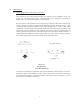
1.0 DESCRIPTION 1.1 General Information and Principles of Operation Your E-Series reverse osmosis (RO) machine is a durable piece of equipment which, with proper care, will last for many years. These instructions give operating and maintenance details vital to the sustained performance of the machine. Reverse osmosis is the separation of one component of a solution from another component by means of pressures exerted on a semipermeable membrane element.
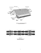
Figure 1.2 - Membrane Element with Interconnectors Figure 1.
Some operating definitions are provided to help you further understand your machine: Permeate Rate [Product Water Rate (Qp)] is the flow rate of purified water which has passed through the membrane element and out of the membrane element housing; expressed in gal/min (gpm) or gal/hr (gph) [in metric, liter/min (Lpm) or cubic meters/hour (m3/h)]. Specified permeate rates are normally at 77ºF (25ºC).
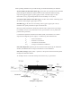
Given the system case in Figure 1.4 (Principles of Operation): Average Concentration (Cavg) = (Cf) 100 mg/L + (Cc) 146.9 mg/L 2 (Cavg) = 123.5 mg/L TDS Rejection = Passage = Recovery = (Cavg) 123.5 - (Cp) 6.2 x 100 = 95% (Cavg) 123.5 (Cp) = 6.2 (Cavg) = 123.5 x 100 = 5.0% (Qp) 2 gpm x 100 = 33% (Qf) 6 gpm Flow Description - The feed water passes through a replaceable 5-micron cartridge pre-filter which removes bulk suspended solids. Filtered water then flows to the inlet control valve.
Example: 1.3 E4H-21K/ECN, 230, 6, 50-75 • E4H indicates the machine series • H indicates horizontal membrane element housing configuration • 21K indicates the rated permeate flow in thousands of gallons per day @ 77ºF (25ºC),(i.e.
1.4.
• 1.5 Alarms included: low inlet pressure, high amp draw, high / low pH Specifications for E-Series Machines 1.5.1 Feed Water Requirements Table 1.1 Feed Water Requirements Temperature 35° - 77°F (2° - 25°C) Not to exceed 85°F (29°C) unless specifically designed for higher temperatures Inlet Pressure Minimum: 30 psig (2.1 barg) Maximum: 60 psig (4.1 barg) Chlorine (continuous feed) Operating pH Pre-filter Inlet Connections 1.5.
1.5.3 Concentrate Flow Rate Factory set as stated on serial number label Concentrate Outlet: 1.5.4 Typical Pure Water Recovery: 1.5.5 50 - 75% Final Operating Pressure Minimum: Maximum: 1.5.6 1-inch FNPT 200 psig (13.8 barg) 235 psig (16.2 barg) Pump Multi-stage centrifugal, approximate primary operating pressure of 190 psig (13.1 barg), excluding line pressure. 1.5.
Figure 1.2 Typical Membrane Element Rejections/Passages SALTS To estimate passage of salts for membrane elements other than SEPAHR, take the passage for the SEPA-HR and multiply by the factor for the passage for the particular membrane element.
2.0 INSTALLATION 2.1 Mounting E4H machines are equipped with a stand alone frame, 61-inch (155-cm) H x 132-inch (335 cm) W x 34-inch (86 cm) D, which supports the machine. At least 45 inches (114 cm) of space should be allowed on each end of the membrane element housings for removal and loading of membrane elements. If 45-inches (114 cm) are not available, the entire membrane element housing may need to be removed for membrane element changes. 2.2 Piping 2.2.
2.2.4 Permeate Outlet Connection Install the CIP valve on the permeate outlet tee. The pure water (permeate) should be transported to the point of use via non-corroding-type tubing, pipe, or hose. Examples are: food-grade flexible nylon tubing, stainless steel tubing, or PVC hose. The permeate outlet is 1-inch FNPT. 2.
3.0 PREPARATION AND START-UP 3.1 Pretreatment for Water Purification All systems will operate most efficiently on filtered water with a pH of less than 6.5 and a Silt Density Index (SDI) of 5 or below. If the machine is operated on higher pH water, other forms of pretreatment may be necessary. A water analysis prior to start-up of the machine is required.
STEPS 1. Re-check the function and integrity of your pretreatment equipment. Ensure that your water softener, activated carbon filters and iron filters (where applicable) have been leak-checked, backwashed, and thoroughly rinsed for service before starting up your RO unit. 2. Attach the feed water pipe to the inlet of the machine. 3. Check for leaks at all connection points. 4. Turn ON the feed water gradually and check for leaks in the inlet piping.
inlet stream to the RO pump. It is important to balance the operating pressure and the respective flows of these valves to ensure that your machine is operating correctly. It is also important to understand the relationship of these two valves, the pressure gauge, and your RO pump. The pump has a fixed amount of flow produced, and the valves are the control devices to distribute this fixed flow amount. The pressure gauge is an indicator of applied membrane element pressure, at the flows set by the valves.
NOTE: Do not allow the pressure to exceed 250 psi (17.2 bar). If the pressure exceeds 250 psi (17.2 bar), open the concentrate flow control valve until the pressure gauge shows 250 psi (17.2 bar) or less. As the machine purges the air and fills with water, the pressure will gradually increase. You should see water flowing through the permeate and concentrate flow meters. If you do not see flow, turn the machine OFF and return to Step 1. WARNING: 16.
Once the desired flow rate is achieved [250 psi (17.2 bar) operating pressure] no further valve adjustment is needed. The table below shows flow rates at 50%, 66% and 75% recovery for the E4H models. Use this table in adjusting flow rates. NOTE: Permeate flow rates are dependent upon temperature and conditions at your site. Contact your dealer if you have any questions. Table 3.
. A Daily Log Sheet (Section 10.0) which includes general operating conditions (pressures, flows, concentrations, pH, and pretreatment conditions), and routine or special maintenance (flushing or cleaning as needed) must be kept. This Daily Log Sheet will be required by GE Osmonics if a warranty question arises.
4.0 OPERATION AND MAINTENANCE The operation and maintenance of your GE Osmonics E4H Machine is relatively simple but requires regular data recording and routine preventative maintenance. We cannot emphasize too strongly the importance of filling out the daily log sheet during each operating shift. A data sheet was filled out upon start-up containing pertinent facts on the operation of your machine.
4.3 Flushing The machine should be flushed at least daily to remove sediment from membrane element surfaces. To flush the unit: STEPS 1. Open the concentrate valve until the pressure gauge indicates the minimum pressure designated on the nameplate. This increases the flushing action on the membrane element. NOTE: If pressure will not decrease to designated pressure, or if the concentrate rate does not increase when the valve is opened, the valve may be plugged. 2.
Table 4.4 Dry Chemical Cleaners Description Part Number Quantity Osmo AD-20 Dry acid-surfactant for cleaning TLC, PA and CA membrane elements. 1155420 1155421 1155422 1155423 8 x 4 lb. pkgs/case 45 lb. pail 100 lb. key 300 lb. drum Osmo AK-110 High pH alkaline cleaner for PA membrane elements. Recommended for situations where microbial fouling is a problem. DO NOT use on CA membrane elements. 1155416 1155417 1155418 1155419 8 x 4 lb. pkgs/case 45 lb. pail 100 lb. key 300 lb.
4. Turn the CIP ON/OFF switch to the ON position and recirculate the cleaning solution through the machine. The cleaning solution should be recycled for approximately 15 minutes or until the solution temperature reaches 85°F (29°C). If heat rise occurs too quickly, larger volumes of cleaning solution or the use of a heat exchanger will slow the temperature rise. Turn the CIP OFF and allow it to soak for 10 minutes. TLC MEMBRANE NOTE: WARNING: 4.
4.6 3. Remove the tubing connections on the inlets and outlets of the membrane element housings. 4. Open the concentrate valve. 5. Remove the drain plugs from all PVC manifolds. 6. Be sure the flow meters are drained by disconnecting the bottom fitting of each flow meter. 7. Allow the machine to drain for a minimum of eight hours or until the opened ports quit dripping. 8. After draining is complete, reconnect all of the piping.
4.7 7. Inspect the membrane element housing and clean as necessary to remove any contaminants, obstructions, etc. 8. Apply a small amount of O-ring lubricant to all O-rings on the end caps, and the brine seal on the membrane element. 9. Insert the downstream end of the membrane element in the upstream end of the membrane element housing (i.e., load in the direction of flow; the brine seal is on the end of the membrane element that goes in last.
2. Remove all the membrane elements from the membrane element housings in the direction of flow, where possible. If necessary, a membrane element can be removed against the direction of flow. A heavy duty pliers or channel lock pliers may be necessary to pull the old membrane element our of the membrane element housing. 3. To reinstall replacement membrane elements, follow Steps 4 -14 (Section 4.6, Membrane Element Installation). NOTE: Do not operate the machine on water over 85°F (29°C).
5.0 OPTIONAL ACCESSORIES 5.1 Level Controls Float switches, pressurized storage switches or other level controls should be wired into the control circuit line prior to the switch on the unit. The following ensures that the inlet valve, instruments, and pump are not powered when storage tanks are full: float switch assembly with cord, counterweight, and plastic float (used with an atmospheric storage tank). 5.
6.0 TROUBLESHOOTING TROUBLESHOOTING GUIDE SYMPTOM POSSIBLE CAUSES REMEDIES Low operating pressure Insufficient feed water pressure or flow Open the feed pressure, open the feed water valve, check for restrictions. Clogged pre-filter cartridge Replace the pre-filter cartridge. High flow rates Close the concentrate valve, check the permeate and concentrate flow rates and adjust if necessary. Excessive permeate flow may indicate a damaged O-ring.
TROUBLESHOOTING GUIDE SYMPTOM POSSIBLE CAUSES REMEDIES Low permeate flow rate (continued) Dirty or fouled membrane elements Flush and clean the membrane elements. Operating on cold water less than 55ºF (13ºC) Install a hot/cold feed water tempering valve if more permeate flow is needed. Operate with a feed water temperature of 72º - 77ºF (22º - 25ºC). Membrane elements installed backwards or damaged concentrate seal Install membrane elements in the direction of fluid flow.
TROUBLESHOOTING GUIDE SYMPTOM POSSIBLE CAUSES REMEDIES High operating pressure Recycle or concentrate valve plugged Disassemble the plumbing to the recycle valve and remove foreign particles. Check the concentrate valve stem. Inaccurate pressure gauge Replace or calibrate the gauge as required. Restricted or reduced permeate flow rate See possible causes for low permeate rate.
TROUBLESHOOTING GUIDE SYMPTOM POSSIBLE CAUSES REMEDIES Declining rejection (high permeate conductivity) (continued) O-ring seal broken or damaged Replace the O-ring, check the sealing surfaces on the O-ring groove, interconnectors, and end caps. Replace damaged parts. Change in incoming water quality Open the concentrate valve and flush. Test the water for pH, hardness, TDS, and iron content. A water analysis should be sent to GE Osmonics.
TROUBLESHOOTING GUIDE SYMPTOM POSSIBLE CAUSES REMEDIES Electrical machine shutdown Alarm condition has turned machine OFF Restart the machine by pushing the alarm bypass. Check all possible alarm conditions: inlet pressure or motor starter overload. Motor starter overloaded, heater tripped Turn the switch OFF; rest the heater(s). Check the motor AMP draw and the line voltage. Timing relay defective/burned out Replace the relay.
7.0 RETURN GOODS AUTHORIZATION (RGA) PROCEDURE If you wish to return good for repair, warranty evaluation and/or credit, please have your original sales order or invoice available when you call GE Osmonics. Call (800) 848-1750 and ask to speak with Customer Service. A GE Osmonics Customer Service representative will provide instructions and a return authorization number which needs to be clearly written on the outside of the box used to ship your materials.
8.0 WARRANTY Warranty Terms Subject to the terms and conditions set forth hereinafter, Seller (GE Osmonics, Inc.
workmanship. Required or replaced products or components shall be returned to the Buyer by the Seller, freight prepaid by Seller, via UPS ground or best way surface freight. In genuine emergency situation, Seller will (at Seller’s sole option) forward replacement parts to Buyer without waiting for authorized return of the questionable part(s). In such cases, Buyer will issue a purchase order or other payment guarantee prior to shipment.
9.
35
36 = = = = = = = PRESSURE CONCENTRATE (BLOW-BY) Qc PERMEATE (PURE WATER) Qp RESISTANCE TEMPERATURE RECYCLE CONDUCTIVITY This is a template. Make copies as needed. *Symbols: Q - Flow Rate; C - Conductivity Reference the Troubleshooting Guide in your Instruction Manual where trends or differences are noted.
For more information: Call (952) 933 - 2277 for additional information (800) 848 - 1750 in the U.S., or visit www.gewater.com.