Installation Instructions I Questions? Call 800.GE.CARES (800.432.2737)or Over the Range Microwave Oven Visit our Website at: GEAppliances.com I BEFORE YOU BEGIN Read these instructions completely and carefully. • IMPORTANT instructions - S_ve these for local inspector's use. • IMPORTANT - Obse, ve_ll governing • codes and ordinances. Note to Installer - Be sure to leave these insuuctions with the Consume_. • Note to Consumer instructions - Keep these for flm_re reference.
Installation Instructions [] CONTENTS information Important Safety Instructions .................................. .......................................... Damage - Shipment/Installation 4, 5 .............................. Tools You Will Need ................................................ 7 Mounting Space ...................................................... 7 Placement of Mounting Removing Plate the Mounting Plate ...................... Determining 9 Wall Plate I,ocafion .........
Installation Instructions IMPORTANT SAFETY INSTRUCTIONS ELECTRICAL REQUIREMENTS A qualified elecuician must perform a ground confinuit T check on tim wall receptacle before beginning the installation to ensure that the outlet box is properly grounded. If not properly grounded, or if the wall receptacle does not meet electrical requirements noted (under EI,ECTRICAI, REQUIREMENTS), a qualified elecuician should be employed to correct any deficiencies. Product ra6ng is 120 volts AC, 60 Hertz, 13.
Installation Instructions HOOD EXHAUST NOTE: outside. Read these next two pages only if you plan to vent your exhaust to the If you plan to recirculate the air back into the room, proceed to page 6. OUTSIDETOP EXHAUST (EXAMPLE ONLY) The following chart describes an example of one possible ductwork installation. EQUIVALENT LENGTH DUCT PIECES 12 Ft.Straight Duct RoofCap (6" Round) TransitionAdaptor* Rectangular-to-Round 12 Ft. 24 Ft. x x x 5 Ft. NUMBER USED = EQUIVALENT LENGTH (1) 24 Ft.
Installation Instructions Maximum NOTE: If you need to install ducts, note that tile total duct length of 3¼" x 10" rectangular or 6" diameter round duct should not exceed 140 equivalent feet. Outside ventilation requires a HOOD EXHAUST Read tile following carefllll> For satisfactory' air movement, tile total duct length of 3¼" x 10" rectangular ov 6" diameter round duct should not exceed 140 equivalent feet. DUCT.
Installation Instructions DAMAGE - SHIPMENT/ INSTALLATION • If the unit is damaged to the store in which replacement.
Installation Instructions TOOLS YOU WILL NEED Ruleror tapemeasureand # 1 and#2 Phillipsscrewdriver Tin snips(for cutting damper,if required) Pencil t edge Scissors (to cut template, if necessary) Electricdrill with r_c", W' and%" drill bits 0 Gloves Studfinder or Saw (saber,hole or keyhole) Safetygoggles MOUNTING Level Carpentersquare (optional) Fillerblocksor scrap wood pieces,if needed for top cabinetspacing (usedon recessedbottom cabinet installationsonly) Hammer(optional) Ductandmaskingt
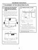
Installation Instructions PLACEMENT A-_ OF THE MOUNTING EMOVING THE MICROWAVE OVEN FROM THE CARTON/ REMOVING THE MOUNTING PLATE _i_ Remove the installation [] tray and the the SDrofoam small instructions, hardware protecting bag. the _] FINDING THE WALL STUDS filters, glass Do flont not remove of the oven. ' Fold back all 4 carton flaps fldly against carton sides. onto Then the top careflflly side.
Installation Instructions I-_ DETERMINING Plate position cabinet WALL PLATE LOCATION UNDER YOUR CABINET - beneath Plate position - beneath cabinet bottom flat bottom framed MountingPlateTabs the CabinetBottom recessed Mounting PlateTabs Touchingthe Back Frame oO ",,% %. 30" to Cooktop At least 30", up to 36" Plate position - beneath recessed bottom cabinet with front overhang Your cabinets may have decorative trim that interferes with the microwave installation.
Installation Instructions I-_ ALIGNING THE WALL PLATE Hole B HoleC o Drawa Vertical Lineon Wall Centerline ._-_- from Centerof Notches TopCabinet ooooooo oooooooo / AreaE HoleD CAUTION: Wear gloves to avoid cutting fingers on sharp edges. []Draw a vertical line on the wall at the center NOTE: Holes C and D are inside area E. If neifller C nor D is in a stud, find a stud somewhere in area E and draw a fifth circle m line up with the stud.
Installation Instructions INSTALLATION TYPES This microwave oven is designed for adaptauon the following three types of ventilation: A. Outside B. Outside (Choose A, B or C) to NOTE: This microwave is shipped assembled for Outside Top Exhaust (except for non-vented models). Select the type of ventilation required for your installation and proceed to that section. Top Exhaust (Vertical Duet) Back Exhaust (Horizontal Duet) C.
Installation Instructions OUTSIDE TOP EXHAUST INSTALLATION A1. A2. A3. A4. A5. A6. OVERVIEW Attach Mounting Plate to Wall Prepare Top Cabinet Check Damper Operation Mount Microwave Oven Adjust Exhaust Adaptor Gonnect Ductwork I-_ (Vertical Duct) | To use toggle ATrACH THE MOUNTING PLATE TO THE WALL bolts: Spacingfor Toggles MoreThanWall II Mounting Plate _,-_[_Thickness ToggleWings ===m Bolt End _ Attach tim plate to tim wall using toggle bolts.
Installation Instructions USE TOP CABINETTEMPLATE FOR PREPARATION OF TOP CABINET MOUNTTHE OVEN MICROWAVE CAUTION: FoREnSIER You need to drill holes for tile top support screws, a hole large enough for tile power cord to fit through, and a cutout large enough for tile exhaust adaptor. INSTALLATION AND PERSONAL SAFETY, WE RECOMMEND THAT TWO PEOPLE INSTAI_J_ THIS MICROWAVE OVEN. IMPORTANT: Do not grip or use handle during installation.
Installation Instructions MOUNTTHE MICROWAVE OVEN (cont.) ADJUSTTHE ADAPTOR CabinetFront Open the top cabinet and adjust to connect to the house duct. CabinetBottomShelf "_ to Depth of Cabinet Equivalent Recess _djustment Slide the ExhaustAdaptor as Needed MicrowaveOvenTop the microwave [] oven to the top cabinet. CONNECTING Insert 2 self-aligning screws through outer top cabinet holes. Turn two full ictlIns on each screw. []Extend the house duct the exhaust adaptoi.
Installation Instructions OUTSIDE INSTALLATION B1. B2. B3. B4. B5. I-_ BACK EXHAUST (Horizontal Duct) OVERVIEW Prepme Rear Wall Attach Mounting Plate to Dvrall Prepare Top Gabinet Adapt Blower Mount the Mic_owave Oven I-_ PREPARING THE REAR WALL FOR OUTSIDE BACK EXHAUST You need to cut an opening outside exhaust. ATTACH THE MOUNTING PLATE TO THE WALL in the rea_ wall fo_ Attach the plate to the wall using toggle bolts.
Installation Instructions To use toggle bolts: ADAPTING MICROWAVE BLOWER FOR OUTSIDE BACK EXHAUST Spacingfor TogglesMore +l_-,-i*_ ThanWall Thickness ToggleWings i Mounting Plate _;!_ Remove and save the screw that holds the blower motor door closed on the back and the blower retaining screw on the top of the dooL Blower --_,-_, Retaining _ jjBIower Bolt End Scre []Place insert tO the mounting plate against tile wall and the toggle wings into tlle holes in tile wall H1OtlII[ tile plate.
Installation Instructions I-_ _ []Place ADAPTING MICROWAVE BLOWER FOR OUTSIDE BACK EXHAUST (cont.) Rotate blower unit counterclockwise BeforeRotation the blower unit back into the opening. EndA 180 °. After Rotation End A CAUTION: Donot pull stretch the blower unit wiring. wires are not pinched. Microwave Oven Microwave Oven ienlove the wires flom the grooves. [Gently' Reroute the wires through grooves on other of the blower unit.
Installation Instructions CabinetFront I-_ MOUNTTHE OVEN MICROWAVE CabinetBottomShelf Filler Block _ quivalent to Depth of Cabinet Recess Self-AligningScrew CAUTION: FOREASIER MicrowaveOvenTop INSTALLATION AND PERSONAL SAFETY, WE RECOMMEND THAT TWO PEOPLE INSTALL THIS MICROWAVE OVEN. IMPORTANT: Do not during installation. grip or use _i_ Attach _2 handle NOTE: If your cabinet is metal, use tim nylon grommet around the power cord hole to prevent cutting of the cord.
Installation Instructions RECIRCULATING INSTALLATION C1. C2. C3. C4. C5. (Non-Vented Ductless) OVERVIEW Attach Mounting Plate to Wall Prepare Top Cabinet Adapt Blower Mount the Microwave Oven Install Charcoal Filter I_ _ A]WACHTHE MOUNTING PLATE TO THE WALL !! Place the mounting plate against the wall and insert the toggle wings into the holes in the wall to inount the plate.
Installation Instructions ADAPTING MICROWAVE BLOWER FOR RECIRCULATION _] Roll the blower unit 90 ° so that fan blade openings are facing toward the flont of the microwave. _l_ Remove and save the sciew that holds the blower motor door closed on the back and the blower retaining screw on the top of the doon Blower--_,,_g Retaining Screw._, _ Blower Blower .__f_?_N. +_fi>_ _, Backof Microwave Oven _] Open the blower of the microwave door by lifting oven. Remove blower screw. .....
Installation Instructions ADAPTING MICROWAVE BLOWER FOR RECIRCULATION (cont.) [_ Place tile blower unit back MICROWAVE CAUTION: for EASIER into tile opening. CAIYFION: the blower unit wiring. not pinched. MOUNTTHE OVEN Donot Make pull or sure the wires stretch are INSTALLATION AND PERSONAL SAFETY, WE RECOMMEND THAT TWO PEOPLE INSTALL THIS MICROWAVE OVEN. IMPORTANT: Do not during installation.
Installation Instructions MOUNTTHE INSTALLING THE CHARCOAL FILTER MICROWAVE OVEN (cont.) []Insert a self-aligning screw through top center cabinet hole. Temporarily secure the oven by turning the screw at least two full turns after the threads have engaged. (It will be completely tightened later.) Be sure to keep power cord tight. Be careful not to pinch the cord, especially when mounting flush to bottom of cabinet. _ Remove the 3 screws that secure the flont flom the top of the microwave oven.
Installation Instructions BEFORE YOU USE YOUR MICROWAVE IT[ Make sure the microwave oven has been installed according to instructions. Remove all packing material microwave oven. I Install turntable Replace % I and ring in cavity. into a dedicated t Ensure proper groundexists/ beforeuse k. Read the Owner's Manual. KEEP INSTALLATION INSTRUCTIONS FOR THE LOCAL INSPECTOR'S USE. flom the house fllse or turn breaker Plug power cord electrical outlet. '_] back on.
t DE68-03709A 49-40616-1 09-09 JR Printed in Malaysia
Instrucciones de instalacion Homo microondas para colocar encima de la estufa gPreguntas? Llame 800.GE.CARES(800.432.2737)o,_i_it_m,_t,a p_gina_n_a,'_d_n: GEAppliances.com ANTES DE EMPEZAR Lea estas instrucciones completa • IMPORTANTE instrucciones para el uso • Nota estas los cddigos inspector para el instalador instrucciones con - Asegfirese de para flmna • La instalacidn apropiada del insmladoL gubernamentales. el consumidor. el consumidor - Guarde esms referencia.
Instrucciones de instalacion _ CONTENIDO Informacion Instrucciones de seguridad importantes .................. Requisitos el6ctricos ................................................ Campana de escape .............................................. Dafios - Envio / Instalaci6n 3 Cdmo preparar 3 Cdmo adaptor el calefactor del microondas para la recirculacidn 4, 5 .................................... 6 Herramientas 7 que necesitarfi .................................... Espacio de montaje .......
Instrucciones de instalacion INSTRUCCIONES DE SEGURIDAD Un elecuicism calificado debe realizar una verificacidn de continuidad de conexidn a tierra en el tomacorriente de pared antes de comenzar la instalacidn para garantizar que la c_tja de disuibucidn tenga una adecuada conexidn a tierra.
Instrucciones de instalacion CAMPANA DE ESCAPE NOTA: Lea las siguientes dos pfiginas solamente si planea ventilar el escape hacia el exterior. Si pot el contrario planea recircular el aire de vuelta hacia el sal6n, continfie en la pfigina 6. ESCAPE SUPERIOR EXTERNO (EJEMPLO SOLAMENTE) La siguiente mbla describe un ejemplo de una posible instalacidn de red de conductos.
Instrucciones de instalacion Longitud NOTA: Si usted necesim insmlar conductos, tenga pendiente que la longimd tot;d del conducto rectangular de 3¼" x 10" o el conducto redondo de 6" de diAmetro debe sobrepasar 140 pies Los codos, transiciones, paredes y tapas de techo, etc., presenmn resistencia adicional al NOTA: Es impormnte que la venfilaci6n sea instalada usando la rata m_is directa y'con la menor canfidad de codos posible. Esto asegura la venfilacidn del escape y ayuda a prevenir bloqueos.
Instrucciones de instalacion PARTES INCLUIDAS DAI_OS - ENV(O / INSTALACION PAQUETE DE ELEMENTOS • Si la unidad se dafia durante la unidad al almac&l donde su reparacidn o reemplazo. el envio, devuelva la adquiri6 para • Si el diente dafia la unidad, reemplazo es responsabilidad la reparacidn del clieme.
Instrucciones de instalacion HERRAMIENTAS Destornilladoresde estrella #1y#2 Tijerasparacortar lat6n (paracortar el regulador de tiro, si es necesario) QUE NECESITARA L@iz Escuadrade carpintero (opcional) Tijeras(paracortar la plantilla, si esnecesario) Taladroel6ctricocon brocasde 3/l_,,,l/2,,y _A,, 8 @===_ Guantes Bloquesde rellenoo pedazosde madera,si son necesariospara rellenarel gabinete(usadossolamente en la instalaci6nde gabinetesapoyados) Detectorde postesde viga e un martillo (opcional) S
Instrucciones de instalacion [ C6MO COLOCAR EL PLATO DE MONTAJE A-I C01VIO REMOVER EL HORNO MICROONDAS DEL EMBALAJE C01VIO REMOVER EL PLATO DE MONTAJE B.1C01VIO ENCONTRAR LOS POSTES DE VIGA EN LA PARED / % Remueva l las instFucciones de insmlacidn, los filuos, la bandeja de crisml, y la bolsa pequefia del equipo. No xemueva el protector flonml de espuma de poliestireno del homo. [] Doble tomlmente hacia auds las cuauo tapas de cartdn hacia los lados opuestos de la c_ja.
Instrucciones de instalacion _-1 COIVIO DETERMINAR LA LOCALIZACION DEBAJO DE SU GABINETE Posicion del plato - debajo de fondo piano Posicion del plato - debajo de gabinetes de fondo apoyado en un marco de gabinetes ",, , DEL PLATO DE MONTAJE Lasorejillasdelplatode montaje tooan el fondo Lasorejillas del plato de montajetocan el marcoposterior delgabinete I III I 30" hasta la estufa Por Io menos 30", hasta 36" Posicion del plato - debajo de gabinetes de fondo apoyado con frente saliente Sus gabi
Instrucciones de instalacion C01VIO ALINEAR EL PLATO DE MONTAJE SOBRE LA PARED i / I I I I I I I I I AgujeroA Agujero C 0 i I Trace una linea vertical en la pared dela lineai a partirdelcentro del centro del gabinete superior Muescas 000000 0000000 AgujeroB 0000000 00000000 ! AgujeroD AreaE PRECAUCION: guantes de protecci6n para evitar cortaduras en sus dedos con los extremos filosos. NOTA: I,os agt{jeros C y D van en el interior del drea E.
Instrucciones de instalacion TIPOS DE INSTALACION Este homo microondas estd disefiado siguientes ues tipos de ventilacidn: A. Escape superior B. Escape posterior C. Recirculaci6n -_ exterior (Condueto exterior (Sin conducto (Condueto para adapmrse a los (Escoja A, B o C) NOTA: Este horno microondas es enviado ya ensamblado para un escape superior exterior (excepto para modelos enviados con escape de recirculaci6n).
Instrucciones de instalacion ESCAPE SUPERIOR EXTERIOR (Conducto vertical) PERSPECTIVA GENERAL DE LA INSTALACION A1. Gdmo adherir el plato de mont;{je a la pared A2. Prepare el gabinete superior A3. Inspeccione la operacidn del regulador de tiro A4. Monte el horno microondas | A5. Ajuste el adapmdor de escape A6.
Instrucciones de instalacion COMO MONTAR MICROONDAS USE LA PLANTILLA DEL GABINETE SUPERIOR PARA LA PREPARACION DEL GABINETE EL HORNO Deber_i perforar agt(jeros para los tornillos de apoyo superiores, un agt{jero suficientemente grande para que el cable el_cuico quepa, y un recorte lo suficientemente grande como para que el adapmdor de escape pueda set inuoducido. PRECAUCION: OBTENER • I,ea las instrucciones sobre GABINETE SUPERIOR.
Instrucciones de instalacion COMO MONTAR EL HORNO MICROONDAS (continuacion) COMO AJUSTAR EL ADAPTADOR DE ESCAPE Abra el gabinete superior y ajuste el adapmdor de escape para conecmrlo al conducto de la casa. Frentedel gabinete Estantedel fonde del gabinete Parteposterior del homo microondas Bloquede relleno Reguladorde tiro T la profundidad del retrocesoa quivalente del gabinete Tornilloautoalineable Paraajustesde lade a lade, desliceel adaptadordel tubo de escapeseg_nsea necesario.
Instrucciones de instalacion ESCAPE POSTERIOR EXTERNO PERSPECTIVA GENERAL DE LA INSTALACION (Conducto horizontal) | B1. Piepme la paxed postexiox B2. Gdmo adherii el plato de mont_je a la paxed B3. Prepare el gabinete supexiox B4. Adapte el calefactor BS.
Instrucciones de instalacion Para usar los tornillos -_l*-_i_ Platode basculantes: I-_ Espaciadores para los basculantes mayores que el ancho de la pared I Alas de mariposa Retire y guarde el tornillo que mantiene cerrada la puerta del motor del ventilador en la parte trasera y el tornillo de retencidn del ventilador en la parte superior de la puerta.
Instrucciones de instalacion C01VIOADAPTAR EL CALEFACTOR DEL MICROONDAS PARA EL ESCAPE POSTERIOR EXTERIOR Coloque la unidad la abertura. del calefactor de (continuacion) en ExtremoA []Rote la unidad 180 ° en sentido agt_ias del relQj. Antes de la rotaci6n contrario a las Extremo B Despu6sde la rotaci6n PRECAUCION: ni estire los cables de que los alambres _e_po_terior Parteposterior del homo microondas [] Suavemente remueva los alambres de las iantlias.
Instrucciones de instalacion Frentedel gabinete _-_ COMO MONTAR MICROONDAS EL HORNO Estantedel fondo del gabinete Bloquede relleno la profundidad delretroceso quivalentea delgabinete T Tornilloautoalineable PRECAUCION: OBTENER UNA Y EN POS DE PARA INSTALACION _ LA SEGURIDAD RECOMIENDA ESTE HORNO PERSONAL, QUE DOS PERSONAS MICROONDAS. Parte superior del homo microondas FACIL SE _ INSTALEN Pegue el horno sea NOTA: esmnte del superior superiores vueltas del horno.
Instrucciones de instalacion RECIRCULACION (Sin conducto de ventilacion) PERSPECTIVA GENERAL DE LA INSTALACION C1. G6mo adherir el plato de mont_je a la pared C2. Prepare el gabinete superior C3. Adapte el calefactor C4. Monte el homo microondas C5. Insmle el filtro de carbonilla I-_ [_] Coloque el plato de mont_{je contra la pared e inserte las alas de mariposa en los agx{jeros de la pared para monmr el plato.
Instrucciones de instalacion I-_ COMO ADAPTAR EL CALEFACTOR Ruede la unidad del calefactor 90 ° de forma tal que las abermras de la paleta del ventilador est_,n orienmdas hacia el frente del microondas. DELMICROONDAS PARA LA RECIRCULACION Retire y guarde el tornillo que mantiene cerrada la puerta del motor del ventilador en la parte trasera y el tornillo de retencidn del ventilador en la parte superior de la puerto. Tornillode _ retenci6ndel _- . Ventilador .J-- ventilador ....
Instrucciones de instalacion COMO ADAPTAR EL CALEFACTOR DEL MICROONDAS PARA LA RECIRCULACION (continuacion) Coloque la unidad en la abermra. del calefactor de C0MO MONTAR MICROONDAS EL HORNO iltlevo p PRECAUCION: Notireni estire los cables del calefactor. Cerci6rese los alambres no estfin pellizcados. de que _4,PRECAUCION: PAPaOBTENER UNAINSTAtaCION MASFACILVEN POS DE LA ]J SEGURIDAD PERSONAL, SE RECOMIENDA DOS PERSONAS INSTALEN ESTE HORNO MICROONDAS.
Instrucciones de instalacion I-_ _Inserte un central tornillo superior temporalmente vueltas de del autoalineaci6n gabinete. girando completas agarrado. Cerci6rese Tenga I-_ COMO MONTAR EL HORNO MICROONDAS (continuacion) a trav6s Asegure el tornillo despu6s de las lo (Luego quedarfin totalmente de mantener el cable el6ctrico cuidado cuando se de monte no pellizcar al nivel fondo dos Abra la puerta y quite el panel.
Instrucciones de instalacion ANTES DE COMENZAR A USAR SU HORNO MICROONDAS -i'7"] -_ I Cercidrese de acuerdo delemueva homo de homo ha sido insmlado conquelas elinstrucciones. todos los materiales microondas. Instale el aro rotatorio la cavidad. '-_ y con % Enchufe '_'1 Lea el Manual del Propiemrio. ['_ GUARDE ESTAS INSTRUCCIONES EL USO DEL INSPECTOR LOCAL. PARA exclusivo el cable el_ctrico en un tomacorriente de 15 a 20 amperios.
t DE68-03709A 49-40616-1 09-09 JR Impreso en Malasia