g EV Charging Station User Manual & Installation Instructions NEMA EVSE CHARGING STATION USER MANUAL & INSTALLATION INSTRUCTIONS WALL-MOUNT PEDESTAL GE EV Charging Station User Manual POLE-MOUNT BACK TO BACK 1 of 86
g EV Charging Station User Manual & Installation Instructions CONTENTS 1 Important Safety and Grounding Instructions ................................................................................................................................... 3 1.1 Safety and Compliance ....................................................................................................................................................................... 3 1.2 Grounding Instructions ...................................
g EV Charging Station User Manual & Installation Instructions 1 Important Safety and Grounding Instructions 1.1 Safety and Compliance WARNING: Read all the instructions before using this product. This device should be supervised when used around children. Do not put fingers into the electric vehicle connector. Do not use this product if the flexible power cord or EV cable are frayed, have broken insulation, or any other signs of damage.
g EV Charging Station User Manual & Installation Instructions 2 Installation Instruction 2.1 Before Installing Before any installation work is performed, study all drawings furnished by the supplier for the particular installation. These include arrangement drawings (front, end, and plan views), connections to the equipment that may be required to meet any local codes (such as mats, screens, or railings) is not furnished. 2.
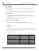
g EV Charging Station User Manual & Installation Instructions Tools Type Slotted Screwdriver Characteristics 3/16” or ¼” Phillips Screwdriver #2 Socket Socket sizes: 7/16”, ¾” Electric Drill Used in the wall mounted and pole mounted installations Wire stripper, hammer, and wall anchors - Table 2 Field cable size: Single Pedestal, Wall Mount and Pole Mount: Cu: 8 AWG, minimum 75 C wire Al: 6 AWG, minimum 75 C wire Double Pedestal: Cu: 8 AWG, minimum 90 C wire Al: 6 AWG, minimum 90 C wire W
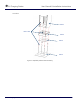
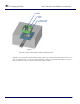
g EV Charging Station User Manual & Installation Instructions Procedure Item 1 Item 5 & 6 Item 3 Item 4 Item 2 Figure 1: Exploded pedestal base assembly GE EV Charging Station User Manual 6 of 86
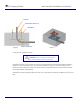
g EV Charging Station User Manual & Installation Instructions CONDUIT MOUNTING TEMPLATE CONCRETE Figure 2 BASE MOUNTING ASSEMBLY Figure 3 Locate area for pedestal location. WARNING: Make sure power to the EVSE is disconnected before performing any task Install two conduits, one for power, and one for communication (if required). Allow approximately 5” length for each conduit above the concrete level as shown in Figure 4. Cut as necessary to final dimensions.
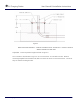
g EV Charging Station User Manual & Installation Instructions 5.50 Figure 4 BASE MOUNTING ASSEMBLY – DURING CONCRETE POUR. ALLOW MIN. 5” CONDUIT LENGTH ABOVE CONCRETE FLOOR LEVEL Adjust (4) ½-13 nuts to position height as shown in Figure 4. Pour concrete to level shown in Figure 4. Do not cover the ½-13 nuts with concrete. Remove mounting template from threaded rods, after concrete has cured. Do not remove the ½-13 nuts as they are used for leveling the skirt.
g EV Charging Station User Manual & Installation Instructions CONDUIT KIOSK SKIRT ½-13 NUT, AND STAR WASHER Figure 5 PEDESTAL SKIRT INSTALLATION, AFTER CONCRETE POUR Install ½-13 nuts and star washers after lowering skirt over matching threaded rods over the ½-13 nuts. Use the bottom ½-13 nuts for leveling the skirt. Fasten nuts and skirt assembly to concrete base, as shown in Figure 5.
g EV Charging Station User Manual & Installation Instructions ½-13 NUT AND ½” STAR WASHER CONCRETE LEVEL Figure 6 Figure 7 Open the door by pressing the round button on the door latch. Insert the Kiosk from top and install ½13 nuts and star washers after lowering skirt over matching threaded rods as shown in the Figures 6 and 7. Torque all the nuts as per the torque specification in Table 1 (recommended tool: 3/8” drive quick release ratchet & 13/16 socket).
g EV Charging Station User Manual & Installation Instructions Ground Bar Fuse Block Ground Bar Incoming Power Fuse Block Incoming Power Cables Connect at Bottom Terminals of Fuse Block Ground Wire Connects to Ground Bars Figure 8 : Power Wire and Ground Wire Connections for Pedestal GE EV Charging Station User Manual 11 of 86
g EV Charging Station User Manual & Installation Instructions Figure 9 : Ethernet Connection to Controller for Pedestal 2.
g EV Charging Station User Manual & Installation Instructions Procedure Item 1 Item 5 & 6 Item 3 Item 4 Item 2 Figure 10: Exploded double pedestal base assembly GE EV Charging Station User Manual 13 of 86
g EV Charging Station User Manual & Installation Instructions CONDUIT MOUNTING TEMPLATE CONCRETE Locate area for pedestal location BASE MOUNTING Figure 11 ASSEMBLY Figure 12 Locate area for double pedestal location. WARNING: Make sure power to the EVSE is disconnected before performing any task Install conduits for power wire and communication wire (if required). Allow approximately 5” length for each conduit above the concrete level as shown in Figure 13. Cut as necessary to final dimensions.
g EV Charging Station User Manual & Installation Instructions 5.50 Figure 13 BASE MOUNTING ASSEMBLY – DURING CONCRETE POUR. ALLOW MIN. 5” CONDUIT LENGTH ABOVE CONCRETE FLOOR LEVEL Adjust (4) ½-13 nuts to position height as shown in Figure 13. Pour concrete to level shown in Figure 13. Do not cover the ½-13 nuts with concrete. Remove mounting template from threaded rods after concrete has cured. Do not remove ½-13 nuts as they are used for leveling the skirt.
g EV Charging Station User Manual & Installation Instructions CONDUIT KIOSK SKIRT ½-13 NUT, AND STAR WASHER DOUBLE PEDESTAL SKIRT INSTALLATION, AFTER Figure 14 DOUBLE PEDESTAL SKIRT INSTALLATION, AFTER CONCRETE POUR Install ½-13 nuts and star washers after lowering skirt over matching threaded rods over the ½-13 nuts. Use the bottom ½-13 nuts for leveling the skirt. Fasten nuts and skirt assembly to concrete base, as shown in Figure 14. Torque nuts per specification Table 1.
g EV Charging Station User Manual & Installation Instructions ½-13 NUT AND ½” STAR WASHER CONCRETE LEVEL Figure 15 Figure 16 Open the door by pressing the round button on the door latch. Insert the Kiosk from top and install ½13 nuts and star washers after lowering skirt over matching threaded rods as shown in Figures 15 and 16.
g EV Charging Station User Manual & Installation Instructions Fuse Blocks Ground Bars Incoming Power Fuse Block 1 Fuse Block 2 Ground Bar 2 Ground Bar 1 Incoming Power Cables Connect at Bottom Terminals of Fuse Blocks Ground Wires Connect to Ground Bars Figure 17 : Power Wire and Ground Wire Connections for Double Pedestal GE EV Charging Station User Manual 18 of 86
g EV Charging Station User Manual & Installation Instructions Controller 2 Controller 1 Figure 18: Ethernet Connection to Controller for Double Pedestal 2.6 Wall-Mounted Bill of materials ITEM DESCRIPTION 1 Kiosk Unit 2 Wall Bracket Assembly 3 Hex. Nuts ¼”-20 4 5 Sealing Washer, ¼” dia.
g EV Charging Station User Manual & Installation Instructions ensure meet UL and American Disability Act compliance. This will ensure the critical height shown in Figure 21. IMPORTANT: Exercise extreme caution when drilling holes in the wall. Make sure there are no electrical cables. Figure 19: Wall-Mount Bracket Holes Min: 19” Max: 25” Figure 20: Wall-Mount Bracket Fasten the wall bracket to the wall. Refer to Table 6 for recommended wall mounting fasteners.
g EV Charging Station User Manual & Installation Instructions MIN: 18” MAX: 24” Figure 21: Wall Mount Installation, Critical Dimension GE EV Charging Station User Manual 21 of 86
g EV Charging Station User Manual & Installation Instructions Wall Mount EVSE Mounting Fasteners Fastener Type Supplier Part Number Qty Application 3/8" x 1-7/8" Concrete Anchor McMaster-Carr 96892A258 6 Concrete Wall Tapcon LDT38134 6 Concrete Wall McMaster-Carr 95526A525 3 Stud Wall Image Pre-drill hole dia. 3/8" 3/8" x 1-3/4" Concrete Hex Screw Pre-drill hole dia. 5/16" 3/8" x 2" Hex Head Lag Bolt Pre-drill hole dia. 3/8" Hardwood (into wood stud) Pre-drill hole dia.
g EV Charging Station User Manual & Installation Instructions The cables must extend 16” to 24” above the wall surface, or according to local codes. Pull L1, L2 and ground wire into the enclosure assembly through the conduit hub. Similarly pull the communication cable into the enclosure assembly through the second conduit. IMPORTANT: EV Charging Station is rated for 208-240V power only. The EVSE must be connected to a grounded, metal, permanent wiring system, or an equipment grounding conductor.
g EV Charging Station User Manual & Installation Instructions In case of RFID sensor, the communication cable is connected to the Ethernet connector on the controller, just like the pedestal as shown in Figure 9.
g EV Charging Station User Manual & Installation Instructions Figure 24: Wall-Mount Conduit Installation Default (left) and Alternate (right) Fitting Locations 2.7 Pole-Mounted Bill of materials ITEM 1 2 3 4 5 6 7 DESCRIPTION Kiosk Unit Pole-bracket Assembly Band Clamp Hex.
g EV Charging Station User Manual & Installation Instructions Procedure WARNING: Make sure power to the EVSE is disconnected before performing any task IMPORTANT: Possible pole diameters for these EVSE units are 8” to 12”. Drill two holes of diameter 1 1/8” on the pole in the location shown in Figure 25. One hole is to bring the power cables and the other for communication cable into the enclosure.
g EV Charging Station User Manual & Installation Instructions Figure 26: Pole Mount Installation, Critical Dimension Optionally, the power wire can be run through the bottom of the enclosure. See page 29. Insert the threaded portion of the conduit hub into the enclosure hole and fasten the conduit hub using the nut. Connect ¾” conduit nipple (Installer supplied) with minimum 3” length up to 4” length to the conduit hub.
g EV Charging Station User Manual & Installation Instructions Figure 27 : Mounting bracket alighnment to the holes The cables must extend 16” to 24” above the pole surface, or according to local codes. Pull L1, L2 and ground wire into the enclosure assembly through the conduit hub. Similarly pull the communication cable into the enclosure assembly through the second conduit. Install the Kiosk pole mounted unit, using the nuts and sealing washers as shown in Figure 28.
g EV Charging Station User Manual & Installation Instructions Figure 28: Pole-Mount Installation, Exploded View IMPORTANT: EV Charging Station is rated for 208-240V power only. The EVSE must be connected to a grounded, metal, permanent wiring system, or an equipment grounding conductor. This should be run with circuit conductors and connected to the equipment grounding bar or lead on the EVSE. Connections to the EVSE shall comply with all applicable electrical codes and ordinances.
g EV Charging Station User Manual & Installation Instructions CONDUIT HUB PLUG Figure 29: Pole-Mount Conduit Using Side Fittings Installations GE EV Charging Station User Manual Figure 30: Alternate Pole-Mount Conduit Installation Using Bottom Knockouts 30 of 86
g EV Charging Station User Manual & Installation Instructions 2.8 Accessory Kits The EV Charging Station offers the following accessory kits: Ordering Number EVRP01 EVRP02 EVRP03 EV100CD EVRCW50 EVRCG50 EVPMBAND Description RFID enrollment reader CM5321CL USB – 13.45MHz RFID enrollment reader CM5325CL USB – 125kHz RFID enrollment reader RP40 USB - universal CD with standalone SW EV100 Pack of 10 white RIFD cards Pack of 10 GE US RFID cards Pole mount strap installation kit - Table 8 - 2.
g EV Charging Station Ordering Number EVDSCTL01 EVDSCTL02 EVDSCTL03 EVDSCTL04 EVDSCTL05 EVDSCTL06 EVDSCTL07 EVDSCTL08 EVDSLED01 EVDSLED02 EVDSLED03 EVDSRR01 EVDSVFD01 EVDSDR01 EVDSDR02 EVDSFIX01 EVDSSK01 EVDSCBL01-20 EVDSCBL02-20 EVDSCBL03-20 EVDSPD01 EVDSCT01 EVDSCR01 EVDSKIT01 EVDSKIT02 EVDSKIT03 EVDSKIT04 EVDSKIT05 EVDSKIT06 EVDSKIT07 EVDSKIT08 EVDSLBL01 EVDSMAN01 User Manual & Installation Instructions Description EVSE WALLMOUNT - BASIC - Controller Replacement + harness EVSE WALLMOUNT WITH RFID - Con
g EV Charging Station User Manual & Installation Instructions 2.9.1 RFID This section describes how to install the RFID hardware for Pedestal, Wall Mounted and Pole Mounted EVSE units only. For the Back to Back EVSE unit RFID upgrade, contact a GE representative by calling 1-800-GE1STOP.
g EV Charging Station User Manual & Installation Instructions Figure 32: Metal plate, inside view Next, attach the RFID mounting plate to the outside of the EVSE enclosure as shown in Figure 33 and 34, using the hardware provided with RFID.
g EV Charging Station User Manual & Installation Instructions Figure 34: RFID mounting plate, inside view Slide the RFID cable through the open hole as shown in Figure 35, and attach the RFID to its mounting plate as shown in Figure 36 using the tamper-proof screw provided.
g EV Charging Station User Manual & Installation Instructions Figure 36: RFID tamper-proof screw Slide the threaded gland and seal over the RFID cable from the inside of the enclosure and screw it into the threaded hole. Then slide the RFID gland nut over the cable and screw it over the seal and threaded gland. Refer to Figure 37 and 38 below.
g EV Charging Station User Manual & Installation Instructions Figure 37: RFID gland assembly Figure 38: RFID gland assembly GE EV Charging Station User Manual 37 of 86
g EV Charging Station User Manual & Installation Instructions Secure the individual wires in the RFID cable inside the provided Phoenix connector, as shown in Figures 39 and 40. Figure 39: RFID Phoenix Connector Figure 40: RFID wiring Attach the Phoenix connector to the controller in its designated location, as shown in Figure 41 and 42. Make sure to press the Phoenix collector fully into the female socket.
g EV Charging Station User Manual & Installation Instructions Figure 41: RFID Connection Location Figure 42: RFID Connection Location GE EV Charging Station User Manual 39 of 86
g EV Charging Station User Manual & Installation Instructions Once the hardware installation is complete, refer to the software installation guide provided with the RFID package. 2.9.2 VFD WARNING: Make sure power to the EVSE is disconnected before performing any task This section describes how to install the VFD for Pedestal, Wall Mounted and Pole Mounted EVSE units only. For the Back to Back EVSE unit VFD replacement, contact a GE representative by calling 1800-GE1STOP.
g EV Charging Station User Manual & Installation Instructions Figure 44: 3 of 8 10/32” mounting nuts diplayed Remove the RFID unit (or the metal plate and gasket if no RFID has been provided) from the VFID mounting assembly as described in Section 2.9.1. Install the new VFD/RFID mounting assembly, shown in Figure 45 and Figure 46.
g EV Charging Station User Manual & Installation Instructions Figure 45: VFD/RFID mounting plate, front view Figure 46: VFD/RFID mounting plate, back view Re-attach the RFID unit or metal plate as described in Section 2.9.1. 2.9.3 Holding Socket WARNING: Make sure power to the EVSE is disconnected before performing any task This section describes how to install the holding socket for Pedestal, Wall Mounted and Pole Mounted EVSE units only.
g EV Charging Station User Manual & Installation Instructions Figure 47: Holding Socket Phoenix Connection Remove the holding socket by unscrewing the four tamper-proof placement screws on the front face of the EVSE enclosure, shown in Figure 48.
g EV Charging Station User Manual & Installation Instructions After the old holding socket is removed, insert the replacement holding socket and tighten the placement screws. Re-connect the holding socket wire to the Phoenix connector, and re-connect the Phoenix connector to the controller. 2.9.4 Service Door WARNING: Make sure power to the EVSE is disconnected before performing any task Remove the service door. Remove the door ground wire from door ground stud, shown in Figure 49.
g EV Charging Station 2.10 User Manual & Installation Instructions Wiring Diagram The wiring diagram shown in Figure 50 is applicable for all NEMA EVSE units and is included as a reference.
g EV Charging Station User Manual & Installation Instructions 3 User Manual 3.1 Receiving Upon receipt of shipment, examine the package for damage that may have been sustained in transit. If the shipping container must be opened outdoors, take proper precautions to prevent the entrance of moisture. While unpacking, examine the product for broken, bent, or loose parts or other damage.
g EV Charging Station User Manual & Installation Instructions 3.2 Basic User Instructions Status Indicator Vacuum Fluorescent Display (VFD) RFID Reader SAE J1772 compliant connector Charging Cord Figure 51 : EVSE Basic Features Status Indicator: The status indicator at the top of the EVSE displays the state of the EVSE. The key to the colors displayed on the status indicator is shown on a label directly right of the EVSE handle.
g EV Charging Station User Manual & Installation Instructions Vacuum Fluorescent Display (VFD): The VFD serves to prompt the user to do certain things, such as connect to vehicle or return plug to socket. It also displays useful information such as charging time and fault information. RFID Reader The RFID is responsible for maintaining and processing authorization of users for the EV Charging Station, and is available as an option. When the RFID is idle, the RFID LED is red.
g EV Charging Station User Manual & Installation Instructions Figure 53: EVSE during card swipe After the access card is swiped, the RFID LED returns to red until authorization is successful. Once authorized, the RFID LED will return to green until the transaction is ended when the vehicle is disconnected. If authorization is denied, the RFID LED remains red and the VFD will display the “denied” message.
g EV Charging Station User Manual & Installation Instructions AMBER indicates that the vehicle is charging. While charging, the VFD will display the amount of charging time elapsed and total energy drawn. Disconnect from Vehicle: The EVSE can be disconnected from the vehicle at any time. • Press and hold the button on top of the EVSE handle and pull the EVSE handle away from the vehicle inlet socket. The VFD will prompt to replace the handle to the EVSE holder.
g EV Charging Station User Manual & Installation Instructions The EVSE internally monitors its operating performance. If there is a failure of its performance, the status indicator on the EVSE will indicate RED and lockout. Overvoltage/Undervoltage Faults: The EVSE monitors line voltage and cuts power to the EV if the voltage goes out of range. After 1 minute the EVSE rechecks the voltage and will automatically re-enable charging if the voltage comes back within acceptable range.
g EV Charging Station User Manual & Installation Instructions Technical Characteristics SAE Compliant Vehicle Interface Cable Length AC Max Charging Power Output** Voltage and Current Rating AC Power Input Short Circuit Rating Recommended Service Panel Breaker Ground Fault Protection Cold Load Start Local Area Network Network Communication Protocol Network Security Metering Accuracy RFID Reader Display Screen Standby Power Indoor Ventilation Outdoor Rated Safety Compliance Surge Protection EMI Compliance
g EV Charging Station User Manual & Installation Instructions Family Catalog Type Enclosure Single Pedestal Double Pedestal NEMA 3R NEMA 3R Pole NEMA 3R Wall NEMA 3R Output 208-240V 30A 1 phase 208-240V 30A 1 phase 208-240V 30A 1 phase 208-240V 30A 1 phase No. of Connectors Single Phase Integrated Meter 1 Yes 2 Yes 1 Yes 1 Yes RFID Cat # No Yes No Yes No Yes No Yes EVSN3 EVSRN3 EVDN3 EVDRN3 EVPN3 EVPRN3 EVWN3 EVWRN3 - Table 11 - 3.
g EV Charging Station User Manual & Installation Instructions S6 -Configuration Dip Switch Ethernet Connector J1 Figure 54: EVSE Controller The configuration dip switch has positions 1 thru 8. Switches 1 to 4 are set and locked by the manufacturer, and switch 5 is reserved for future use. Switches 6, 7 and 8 are set at installation of the EVSE into its operational environment.
g EV Charging Station User Manual & Installation Instructions Pushed down on “number” side is the CLOSED position Figure 55: Dip Switch Settings (This picture depicts an example of all CLOSED dip switch positions. For correct settings, refer to below tables) The default settings per SKU are given in below table: 1 Factory setting CLOSED 2 Factory setting CLOSED 3 Factory setting CLOSED 4 Factory setting OPEN 5 6 7 reserved Language settings CLOSED OPEN *) OPEN *) 8 Config.
g EV Charging Station User Manual & Installation Instructions 0x00000004 Fault indicating that the unit has experienced a Ground fault CT test failure, either during the powerup self-test or during charge cycle initialization self-test. Check the ground fault CT (current transformer), connections or the EVSE controller. Disconnecting from the vehicle will clear this fault. If it persists repeatedly the ground fault CT and EVSE controller circuit need to be checked.
g EV Charging Station User Manual & Installation Instructions 0x00001000 Controller has detected that the contactor is still in Closed state after the controller issued a command to open the contactor. Check the Main contactor, system wiring or the controller. This fault can only be cleared by cycling power to the EVSE. With power removed, examine the contactor, the auxiliary feedback circuits, and the connections at J11.
g EV Charging Station User Manual & Installation Instructions 4 Network Setup Instructions This chapter details design recommendations for a GE EV Charging Station Network Infrastructure. Network setup is required for installations that use RFID authentication. It is not required for EVSE that do not use RFID authentication. This section of the installation document covers the options for connecting the charging stations with a PC hosting the EV100 GE EV Charging Station Manager Application software. 4.
g EV Charging Station User Manual & Installation Instructions Any firewall used for a DMZ environment should be a business class system (i.e. Cisco ASA, Checkpoint, SonicWall, etc) and provide a true DMZ capability. Typical SOHO firewalls do NOT provide true DMZ capabilities. GE supports the use of the Cisco ASA5505 firewall and provides settings for its use in this scenario. o Physical Security. Physical security is a necessary consideration in any installation of this type.
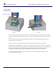
g EV Charging Station User Manual & Installation Instructions Figure 56 2. Right Click on Local Area Network and select to open the properties Window Right click, select “Properties” Figure 57 3. Scroll through the protocols used by the local area connection to find the Internet Protocol (TCP/IP). Select this protocol by clicking on it and then click on the Properties button to open the window that will allow you to set the IP address and Subnet mask.
g EV Charging Station User Manual & Installation Instructions 4. Click the Radio button to “Use the following IP Address” and then enter both the IP address and Subnet mask as shown. IP Address Subnet Mask Default Gateway 192.168.2.19 255.255.255.0 Leave Blank 5. Click OK and Close both properties windows to save your settings *Note: Proxy Settings In Internet Explorer, open “Tools”>”Internet Options”, click on “Connections” tab and then “LAN Settings”: Enable “Use automatic configuration script”.
g EV Charging Station User Manual & Installation Instructions 2. It is recommended to use a crossed Ethernet cable for direct connectivity between the EVSE and the service laptop or PC.
g EV Charging Station User Manual & Installation Instructions 3. With the power removed, change the position of switch 8 on the S6 to: Switch 8 – Open (Configuration server interface) Keep the other switches in their original position. This Dip-Switch configuration will enable the maintenance interface used during the initial installation of the EVSE. 4. Switch on EVSE main Circuit Breaker to power up the EVSE in configuration mode a.
g EV Charging Station User Manual & Installation Instructions 7. The Controller will invoke the following page: Figure 62: Configuration Server Entry Screen 8.
g EV Charging Station User Manual & Installation Instructions Note: The default values normally need not be changed if the EVSE in question is used in a nonRFID authentication mode.
g EV Charging Station User Manual & Installation Instructions 9. In the EVSE configuration page modify settings as required. The correct settings depend on the chosen network architecture and are described in a later chapter in detail. There are 3 options for configuration: No RFID Authentication (default) RFID authentication in standalone network (see later chapter) RFID authentication in firewalled network (see later chapter) After the desired settings were configured click on “Save”.
g EV Charging Station User Manual & Installation Instructions 4.4 Recommended Network Designs for RFID Authentication It is strongly recommended using one of below network settings, as those are providing necessary security levels for the Charging Station System network and other parts of the network. 4.4.1 Option 1: Stand-alone Network Configuration In this design the charging station network and its associated host system are not connected to the customer network at all.
g EV Charging Station User Manual & Installation Instructions EVSE IP On initial power up the EVSE IP address will default to 192.168.2.2 This must be changed to an appropriate address based on the network configuration. Failure to change the IP address setting will impact the ability to bring up subsequent charging stations on the network due to IP address collisions. Action required ! Assign IP addresses to the charging stations beginning with 192.168.2.22.
g EV Charging Station User Manual & Installation Instructions Note: In the case of any modification of the “Require authentication for charging” status, or after a reset or replacement of the controller, the Station ID must be modified to a new ID not previously used on this network to avoid transaction data to be lost. Host IP address. By default, the IP address is set to 192.168.2.19. Unless there is a collision with another setup, it is recommended to keep this host address.
g EV Charging Station User Manual & Installation Instructions Note: The Station ID information is how the EV100 application distinguishes between stations in the same network. Make sure you assign different values to each EVSE. Note: In the case of any modification of the “Require authentication for charging” status, or after a reset or replacement of the controller, the Station ID must be modified to a new ID not previously used on this network to avoid transaction data to be lost.
g EV Charging Station User Manual & Installation Instructions To configure the network settings on a PC running Windows XP or Windows 7, press the Start button and open the Control Panel. Select the Network Connections applet. Figure 67: Network Connections This displays the connections currently found on the PC. Select the icon for the Local Area Connection and double click to open the properties for this NIC.
g EV Charging Station User Manual & Installation Instructions Figure 69: Network Settings Option 1 (See the Configuration Server Interface section) Click the Radio button to “Use the following IP Address” and then enter both the IP address and Subnet mask as shown. Set the Ethernet IP address, Subnet Mask, and Default Gateway to the following settings: Host IP Address Host Subnet Mask Host Default Gateway 192.168.2.19 255.255.255.0 Leave Blank Click on OK and close both windows to save your settings.
g EV Charging Station User Manual & Installation Instructions 4.4.2 Option 2: Charging Station Network isolated from Customer Network with Host System in a DMZ. In this design, the charging stations are isolated from the customer network and the host system is within a DMZ providing isolation from BOTH the Charging Station Network AND the Customer Network.
g EV Charging Station User Manual & Installation Instructions EVSE Controller Settings Follow the instructions in the Controller Configuration section to set up each individual EVSE according to the following settings: EVSE IP On initial power up the EVSE IP address will default to 192.168.2.2 This must be changed to an appropriate address based on the network configuration.
g EV Charging Station User Manual & Installation Instructions Default Gateway See above Fan wired with contactor EVSE owners with indoor installations who want to charge vehicles that require facility fans to be turned on must run signal connections to terminals 4 and 5 of the Power Terminal Block (PTB). The EVSE owner must follow electrical codes to ensure that proper ventilation is allocated for their facility.
g EV Charging Station User Manual & Installation Instructions recommended to configure the EV100 application to use port 9500 (by default) and all EVSE in the network to also use port 9500 (factory default is 9000). Note: The port number on all EVSE in the network must match the port number defined during the EV100 Software installation. Enable DHCP Keep this option disabled at any time. Allow charging if communication is not established By default, this option is not selected.
g EV Charging Station User Manual & Installation Instructions Figure 71 Host PC Settings: In order to set up your Host PC, make sure you have full Windows Administrator rights. Disable any firewalls and all other Ethernet and WiFi connections on this PC. Then follow these steps to configure your TCP/IP settings for communication with the EVSE. The NIC on the host PC should be connected to the ASA5505 firewall port number 0/6.
g EV Charging Station User Manual & Installation Instructions This displays the connections currently found on the PC. Select the icon for the Local Area Connection and double click to open the properties for this NIC. Figure 73: LAN Network Connection Scroll through the protocols used by the local area connection to find the Internet Protocol (TCP/IP).
g EV Charging Station Action required ! User Manual & Installation Instructions Depending on the choice of IP address range above for the configuration of the EVSEs in the network, set the Ethernet IP address, Subnet Mask, and Default Gateway to the corresponding settings: IP Address Subnet Mask Default Gateway 172.25.1.100 255.255.255.0 172.25.1.1 IP Address Subnet Mask Default Gateway 172.26.1.100 255.255.255.0 172.26.1.1 or Click on OK and close both windows to save your settings.
g EV Charging Station User Manual & Installation Instructions 2. Install the SW It is strongly recommended to install the SW in the default location. - Insert CD 1 of the EV100 Application into the CD ROM and launch setup.exe Follow instructions and keep default Port settings of 3306 Once finished with CD 1, insert CD 2 of the EV100 Application and launch setup.
g EV Charging Station User Manual & Installation Instructions Note: A change of the Host PC IP address while the listener service is running requires a restart of the listener service or a reboot of the host PC. For detail instructions reach out to User Manual document included on CD 1. 2. Launch the EV100 Application Start the EV100 Application and log in. Default login is “admin” and the password “admin”. You should now see the stations appear in the list with a green status after at most 5 min.
g EV Charging Station User Manual & Installation Instructions To activate charging, hold the RFID card in front of the reader for 2-3 seconds. Upon successful authentication of that card, the reader LED will turn green after another small delay of 2-3 seconds. Note: For authentication to work, keep the host PC connected and up and running at all times. 4.5 Setup without RFID Authentication Some EVSE models are not equipped with an RFID reader and are not meant to be set up in a network environment.
g EV Charging Station User Manual & Installation Instructions 4.6 Reset Controller to Factory Default Should you have inadvertently changed to a non-default IP setting and cannot remember the IP settings, or simply reverse to default configuration for other reasons, you can reset the controller to the factory default values by following these steps. Note: It is recommended to keep track of the different IP settings for each EVSE by recording them on the form found on the final page of this document.
g EV Charging Station User Manual & Installation Instructions Note: In the case of a network installation with RFID authentication, after a reset of the controller, the Station ID must be modified to a new ID not previously used on this network to avoid transaction data to be lost. 4.7 Trouble Shooting Guide For assistance with EVSE troubleshooting, please refer to the following website: www.geindustrial.
g EV Charging Station User Manual & Installation Instructions EVSE Settings for ID __________________________________ Locality: ________________________________________________ Facility: _________________________________________________ Unit Number: ____________________________________________ Print one page for each EVSE and keep this record in a safe location or inside the corresponding EVSE.
g EV Charging Station User Manual & Installation Instructions * SAVE THESE INSTRUCTIONS* The instructions do not purport to cover all details or variations in equipment nor to provide for every possible contingency to be met in connection with installation, operation or maintenance. Should further information be desired or should particular problems arise which are not covered sufficiently for the purchaser’s purposes, the matter should be referred to the GE company.