Installation Instructions Built-In Dishwashers IDENTIFY YOUR MODEL Locate your full dishwasher model number on the tub wall just inside its door. The model number is 12 digits containing letters and numbers. Identify the 10th digit in your model number. For example: GDT535PSM 6 SS or GDF510PGM 5 SS. If the 10th digit is a 6, follow the instructions on pages 1-32. If the 10th digit is any other number, follow the instructions on pages 33-64.
Installation Instructions Built-In Dishwashers See your Owner’s Manual for details on how to contact us regarding installation questions FOR YOUR SAFETY BEFORE YOU BEGIN Read these instructions completely and carefully. Read and observe all WARNINGS and CAUTIONS shown throughout these instructions. While performing installations described in this booklet, gloves, safety glasses or goggles should be worn. IMPORTANT – Observe all governing codes and ordinances.
Installation Preparation PARTS SUPPLIED IN INSTALLATION PACKAGE: • • • • • • • • Junction box cover #10 hex-head screw Hose clamp Drain hose hanger 2 Plug buttons Toekick (pre-installed on some models) 2 Tub trim pieces (on some models) 2 Mounting brackets for wood countertops or side cabinets • 2 #8-18 x 5/8” Phillips special head screws, to secure dishwasher to underside of countertop or to side cabinets • Insulation pieces (on some models) • Literature, samples and/or coupons Junction Box Cover #10 He
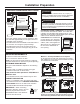
Installation Preparation PREPARE DISHWASHER ENCLOSURE WARNING To reduce the risk of electric shock, fire, or injury to persons, the installer must ensure that the dishwasher is completely enclosed at the time of installation. 33-1/2”34-1/2”+1/4” to 34-3/4” Underside of Underside of Countertop Countertop to Floor to Floor This Wall Area Must be Free of Pipes and Wires ADVERTENCIA 24” Min.
Installation Preparation PREPARE ELECTRICAL WIRING Remove all power leading to the WARNING appliance from the circuit breaker or Alternate Receptacle Location in Adjacent Cabinet fuse box before beginning installation. Failure to do so can result in a risk of electrical shock. 18" Retire todos los conductores de ADVERTENCIA corriente del electrodoméstico 18" de disyuntor o de la caja del fusible antes de comenzar con la instalación.
Installation Preparation PREPARE HOT WATER LINE Water Line Connection NOTE: We recommend copper tubing for the water line, but if you choose to use flexible hose, use GE Appliances WX28X326, flexible braided hose. • If using a flexible braided supply hose, label the hose with the installation date to use as reference. Flexible braided hoses, elbows and gaskets should be replaced in 5 years. • The water supply line (3/8” copper tubing or flexible • Turn off the water supply.
Dishwasher Installation STEP 1 PREPARATION STEP 2 CHECK DOOR BALANCE (CONT.
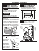
Dishwasher Installation STEP 3 REMOVE WOOD BASE, INSTALL LEVELING LEGS STEP 5 POSITION WATER LINE AND HOUSE WIRING NOTE: Some models have an attached wood base. • Position water supply line and house wiring on the floor of the opening to avoid interference with base of dishwasher and components under dishwasher. CAUTION Do not remove wood base until you are ready to install the dishwasher. The dishwasher will tip over when the door is opened if base is removed.
Dishwasher Installation STEP 7 SLIDE DISHWASHER THREE-FOURTHS OF THE WAY INTO CABINET (CONT) STEP 6 INSTALL DRAIN HOSE, THROUGH CABINET (CONT) • Position dishwasher in front of cabinet opening. Insert drain hose into the hole in cabinet side. If a power cord is used, guide the end through a separate cabinet opening. • As you proceed, pull the drain hose through the opening under the sink. Stop pushing when the dishwasher extends about 6 inches forward of adjacent cabinets.
Dishwasher Installation STEP 9 INSTALL MOUNTING BRACKETS STEP 9 INSTALL MOUNTING BRACKETS (CONT.) You will need the mounting brackets set aside in Step 1. You must install the mounting brackets onto the dishwasher tub frame top OR sides prior to sliding the dishwasher into place under the countertop.
Dishwasher Installation STEP 11 LEVEL DISHWASHER STEP 10 PUSH DISHWASHER INTO FINAL POSITION (CONT.) IMPORTANT – Dishwasher must be level for proper dish rack operation, wash performance and door operation. The dishwasher must be leveled left to right and front to back. This ensures the dish racks will not roll in or out on their own, circulation water will flow to the pump inlet, and the door will close without hitting the side of the tub.
Dishwasher Installation STEP 12 POSITION DISHWASHER, SECURE TO COUNTERTOP OR CABINET STEP 12 POSITION DISHWASHER, SECURE TO COUNTERTOP OR CABINET (CONT.) In this step you will need the 2 Phillips special head screws from the screws set aside in Step 1. The dishwasher must be secured to the countertop or the cabinet sides. When the underside of the countertop is wood, use Method 1. Use Method 2 when the underside of the countertop is made of a material, such as granite, that will not accept wood screws.
Dishwasher Installation STEP 14 CONNECT DRAIN LINE (CONT.) STEP 14 CONNECT DRAIN LINE • The hose should have already been detached from the tub at locations indicated. NOTE: Do not remove high drain loop. Do NOT remove hose from here (high drain loop area). Hose Clamp Remove hose, from these areas only, as needed • Connect drain line to air gap, waste tee or disposer using the previously determined method. Secure hose with a hose clamp. Method 1 – Air gap with waste tee or disposer 72” max.
Dishwasher Installation STEP 15 CONNECT POWER SUPPLY STEP 16 PRETEST CHECKLIST If a power cord with plug is already installed proceed to Step 18. Review this list after installing your dishwasher to avoid charges for a service call that is not covered by your Warranty. WARNING • Check to be sure power is OFF.
Dishwasher Installation STEP 17 DISHWASHER WET TEST STEP 18 POSITION SOUND BARRIER AND INSULATION (on some models) • Turn on power supply or plug power cord into outlet, if equipped. • Select a cycle to run and push the Start/Reset pad. • Ensure the door is latched. Dishwasher should start. • Check to be sure that water enters the dishwasher. If water does not enter the dishwasher, check to be sure that water and power are turned on. • Check for leaks under the dishwasher.
Dishwasher Installation STEP 19 INSTALL TOEKICK STEP 20 CHECK THE FOLLOWING NOTE: On some models the toekick may come pre-installed.
NOTE: Product improvement is a continuing endeavor. Therefore, materials, appearance and specifications are subject to change without notice.
Instructions D’Installation Lave-vaisselle encastré Consultez votre Manuel du Propriétaire pour plus de détails sur la façon de nous contacter concernant les questions d’installation POUR VOTRE SÉCURITÉ AVANT DE COMMENCER Veuillez lire attentivement toutes les directives qui suivent. Veuillez lire et observer toutes les mises en garde (AVERTISSEMENT et ATTENTION) données dans les présentes directives.
Préparation pour l’installation PIÈCES FOURNIES DANS L’EMBALLAGE : • • • • • • • • Couvercle de la boîte de jonction Vis à tête hexagonale n° 10 Collier Support de tuyau de vidange 2 Boutons de bouchon Plinthe (préinstallée sur certains modèles) 2 Moulure de cuve (certains modèles) 2 Supports de montage pour comptoirs ou armoires latérales en bois • 2 Vis à tête spéciale Phillips n° 8-18 x 15,8 mm (5/8 po) pour fixer le lave-vaisselle au dessous du comptoir ou armoires latérales • Pièces isolantes (certain
Préparation pour l’installation PRÉPARATION DE L’OUVERTURE DANS LES ARMOIRES 33-1/2 po to 34-3/4 po du dessous du comptoir au plancher Le mur du fond doit être exempt de tuyaux ou de fils La partie ombrée est réservée à la plomberie et à l’électricité AVERTISSEMENT Pour réduire les risques de choc électrique, d’incendie ou de blessures, l’installateur doit s’assurer que le lave-vaisselle est complètement encastré au moment de l’installation.
Préparation pour l’installation PRÉPARATION DU CÂBLAGE ÉLECTRIQUE AVERTISSEMENT Autre emplacement possible pour la prise de courant dans une armoire adjacente Avant de commencer l’installation, coupez toute alimentation menant de l’appareil au disjoncteur ou au fusible. Dans le cas contraire, vous pourriez être victime d’une décharge électrique.
Préparation pour l’installation PRÉPARATION DE L’ALIMENTATION EN EAU CHAUDE Raccordement de la conduite d’eau chaude • Si vous utilisez un boyau flexible tressé, étiquetez le boyau et indiquez la date d’installation à des fins de référence. Les boyaux flexibles, coudes et joints tressés doivent être remplacés dans 5 ans. REMARQUE: Nous recommandons l’utilisation d’un tuyau en cuivre pour la conduite d’alimentation en eau, mais vous pouvez choisir un boyau flexible tressé no WX28X326 de GE Appliances.
Installation du lave-vaisselle ÉTAPE 2 VÉRIFICATION DE L’ÉQUILIBRE DE LA PORTE (SUITE) ÉTAPE 1 PRÉPARATION Prenez les pièces fournies dans l’emballage et mettez-les de côté: • La porte est correctement équilibrée si, étant ouverte, elle se referme d’elle-même à l’intérieur de 20° de la verticale, reste en position de 20° à 70°, et s’ouvre entièrement au-delà de 70°.
Installation du lave-vaisselle ÉTAPE 5 POSITIONNEMENT DE LA CONDUITE D’EAU ET DE L’ALIMENTATION ÉLECTRIQUE ÉTAPE 3 ENLÈVEMENT DE LA BASE DE BOIS, INSTALLATION DES PIEDS DE NIVELLEMENT • Positionnez la conduite d’alimentation en eau et le câblage de la résidence sur le plancher de l’ouverture afin qu’ils n’entrent pas en contact avec la base du lave-vaisselle et les pièces sous l’appareil. REMARQUE : Certains modèles ont une base en bois attachée.
Installation du lave-vaisselle ÉTAPE 6 INSERTION DU BOYAU DE VIDANGE DANS L’ORIFICE DE L’ARMOIRE (SUITE) ÉTAPE 7 INSERTION AUX TROIS QUARTS DU LAVEVAISSELLE DANS L’OUVERTURE (SUITE) • Placez le lave-vaisselle vis-à-vis de l’ouverture dans les armoires. Insérez le boyau de vidange dans l’orifice que vous avez précédemment percé dans la paroi des armoires. Si l’appareil est doté d’un cordon d’alimentation, faites passer l’extrémité du cordon dans un l’ouverture dans les armoires distinct.
Installation du lave-vaisselle ÉTAPE 9 INSTALLATION DES SUPPORTS DE MONTAGE (SUITE) ÉTAPE 9 INSTALLATION DES SUPPORTS DE MONTAGE Vous aurez besoin des supports de montage mises de côté à l’étape 1. Posez les supports de montage sur les côtés si le comptoir est en granite ou un matériau similaire qui n’accepte pas les vis à bois : Vous devez poser les supports de montage sur le dessus OU les côtés du cadre de la cuve du lave-vaisselle avant de glisser le lave-vaisselle en place sous le comptoir.
Installation du lave-vaisselle ÉTAPE 10 INSTLLATION DU LAVE-VAISSELLE DANS SON EMPLACEMENT DÉFINITIF (SUITE) ÉTAPE 11 MISE DE NIVEAU DU LAVE-VAISSELLE (SUITE) • Enlevez le panier inférieur et placez un niveau sur la porte et sur le rail du panier inférieur, comme indiqué à la figure. • Vérifiez l’alignement du lave-vaisselle avant d’ouvrir la porte afin de prévenir tout dommage au panneau de la porte.
Installation du lave-vaisselle ÉTAPE 12 FIXATION DU LAVEVAISSELLE AU-DESSOUS DU COMPTOIR OU AUX CÔTÉS DES ARMOIRES ÉTAPE 12 FIXATION DU LAVEVAISSELLE AU-DESSOUS DU COMPTOIR OU AUX CÔTÉS DES ARMOIRES (SUITE) Au cours de cette étape, vous aurez besoin des deux vis à tête spéciale Phillips mises de côté à l’étape 1. Le lave-vaisselle doit être fixé au dessous du comptoir ou aux côtés des armoires. Lorsque le dessous du comptoir est en bois, utilisez la Méthode n° 1.
Installation du lave-vaisselle ÉTAPE 14 RACCORDEMENT DU BOYAU DE VIDANGE ÉTAPE 14 RACCORDEMENT DU BOYAU DE VIDANGE (SUITE) • Le tuyau doit déjà avoir été détaché de la baignoire aux emplacements indiqués. REMARQUE : Ne retirez pas la boucle du boyau de vidange supérieur.
Installation du lave-vaisselle ÉTAPE 15 BRANCHEMENT DE L’ALIMENTATION ÉLECTRIQUE ÉTAPE 16 LISTE DE CONTRÔLE PRÉLIMINAIRE Si un cordon d’alimentation pourvu d’une fiche est déjà installé sur l’appareil, passez à l’étape 18.
Installation du lave-vaisselle ÉTAPE 17 ESSAI DU LAVEVAISSELLE AVEC DE L’EAU ÉTAPE 18 INSTALLATION DU MATÉRIAU INSONORISANT ET DU MATÉRIAU ISOLANT (certains modèles) • Rétablissez l’alimentation électrique ou si l’appareil est doté d’un cordon d’alimentation, branchez-le dans la prise de courant murale. Omettez cette étape si le matériau insonorisant est installé sur le lave-vaisselle. • Sélectionnez un cycle à exécuter et pressez la touche Start/Reset (Démarrer/Réinitialiser).
Installation du lave-vaisselle ÉTAPE 19 INSTALLATION DU PANNEAU INFÉRIEUR ÉTAPE 20 VÉRIFIEZ LES POINTS SUIVANTS REMARQUE : Sur certains modèles, l’embout peut être préinstallé.
NOTE: Nous nous efforçons continuellement d’améliorer les produits. Par conséquent, les matériaux, l’aspect et les caractéristiques sont assujettis à des changements sans préavis.
Installation Instructions Built-In Dishwashers See your Owner’s Manual for details on how to contact us regarding installation questions FOR YOUR SAFETY BEFORE YOU BEGIN Read these instructions completely and carefully. Read and observe all WARNINGS and CAUTIONS shown throughout these instructions. WARNING While performing installations described in this booklet, gloves, safety glasses or goggles should be worn.
Installation Preparation PARTS SUPPLIED IN INSTALLATION PACKAGE: • • • • • • • • • • • • Junction box cover and #10 hex-head screw #10 Junction Hose clamp Hex-Head Box Cover Junction Drain hose (approximately 58” long) Box Screw Drain hose hanger 1/2" long 2 #8-18 hex head screws to secure brackets to washer tub frame #8 Hex-Head 2 Plug buttons Mounting Bracket Toekick (pre-installed on some models) Plug Screws Buttons 2 Tub trim pieces (on some models) 2 Mounting brackets for wood countertops or side cabi
Installation Preparation PREPARE DISHWASHER ENCLOSURE WARNING To reduce the risk of electric shock, fire, or injury to persons, the installer must ensure that the dishwasher is completely enclosed at the time of installation. 33-1/2”34-1/2”+1/4” to 34-3/4” Underside of Underside of Countertop Countertop to Floor to Floor This Wall Area Must be Free of Pipes and Wires ADVERTENCIA 24” Min.
Installation Preparation PREPARE ELECTRICAL WIRING Remove all power leading to the WARNING appliance from the circuit breaker or Alternate Receptacle Location in Adjacent Cabinet fuse box before beginning installation. Failure to do so can result in a risk of electrical shock. 18" Retire todos los conductores de ADVERTENCIA corriente del electrodoméstico 18" de disyuntor o de la caja del fusible antes de comenzar con la instalación.
Installation Preparation PREPARE HOT WATER LINE Water Line Connection NOTE: We recommend copper tubing for the water line, but if you choose to use flexible hose, use GE Appliances WX28X326, flexible braided hose. • If using a flexible braided supply hose, label the hose with the installation date to use as reference. Flexible braided hoses, elbows and gaskets should be replaced in 5 years. • The water supply line (3/8” copper tubing or flexible • Turn off the water supply.
Dishwasher Installation STEP 1 PREPARATION STEP 3 REMOVE WOOD BASE, INSTALL LEVELING LEGS Locate the items in the installation package: • • • • • • • • • • Screws Junction box cover Drain hose and clamp Mounting brackets Trim pieces (on some models) Drain hose hanger Insulation pieces (some models) Toekick (pre-installed on some models) Owner’s Manual Product samples and/or coupons CAUTION Do not remove wood base until you are ready to install the dishwasher.
Dishwasher Installation STEP 7 POSITION WATER LINE AND HOUSE WIRING STEP 5 INSTALL 90° ELBOW • Thread 3/4” GHT 90° elbow onto the water valve. Ensure rubber Water Valve gasket is located Bracket between valve and elbow. • Do not overtighten elbow. Water valve bracket could bend or water valve fitting could break. • Position the end of the elbow to face the rear of the dishwasher.
Dishwasher Installation STEP 10 INSTALL TRIM PIECES (on some models) STEP 9 SLIDE DISHWASHER THREE-FOURTHS OF THE WAY INTO CABINET Skip this step if trim is not supplied with the dishwasher. IMPORTANT – Do not push against front panel with knees. Damage will occur. • Grasp the sides of the front panel and slide dishwasher into the opening a few inches at a time. In this step you will need the trim pieces set aside in Step 1. • Position the trim pieces so the lips face toward the dishwasher door.
Dishwasher Installation STEP 11 INSTALL MOUNTING BRACKETS STEP 11 INSTALL MOUNTING BRACKETS (CONT.) You will need the mounting brackets and 2 #8 hexhead screws set aside in Step 1. You must install the mounting brackets onto the dishwasher tub frame top or sides prior to sliding the dishwasher into place under the countertop.
Dishwasher Installation STEP 13 LEVEL DISHWASHER STEP 12 PUSH DISHWASHER INTO FINAL POSITION (CONT.) IMPORTANT – Dishwasher must be level for proper dish rack operation, wash performance and door operation. The dishwasher must be leveled left to right and front to back. This ensures the dish racks will not roll in or out on their own, circulation water will flow to the pump inlet, and the door will close without hitting the side of the tub.
Dishwasher Installation STEP 14 POSITION DISHWASHER, SECURE TO COUNTERTOP OR CABINET STEP 14 POSITION DISHWASHER, SECURE TO COUNTERTOP OR CABINET (CONT.) • Re-check that the dishwasher is squarely positioned in the cabinet at both the top and bottom of the appliance after mounting to the cabinets/countertop. Adjust if necessary.
Dishwasher Installation STEP 16 CONNECT DRAIN LINE (CONT.) STEP 16 CONNECT DRAIN LINE The molded end of the drain hose will fit 5/8” through 1” diameter inlet ports on the air gap, waste tee or disposer. • Determine size of inlet port. • Cut drain hose connector on the marked line, if required, to fit the inlet port. • Connect drain line to air gap, waste tee or disposer using the previously determined method. Secure hose with a screw-type clamp.
Dishwasher Installation STEP 17 CONNECT POWER SUPPLY STEP 18 PRETEST CHECKLIST If a power cord with plug is already installed proceed to Step 18. Review this list after installing your dishwasher to avoid charges for a service call that is not covered by your Warranty. WARNING • Check to be sure power is OFF.
Dishwasher Installation STEP 19 DISHWASHER WET TEST STEP 20 POSITION SOUND BARRIER AND INSULATION (on some models) • Turn on power supply or plug power cord into outlet, if equipped. • Select a cycle to run and push the Start/Reset pad. • Ensure the door is latched. Dishwasher should start. • Check to be sure that water enters the dishwasher. If water does not enter the dishwasher, check to be sure that water and power are turned on. • Check for leaks under the dishwasher.
Dishwasher Installation STEP 21 INSTALL TOEKICK STEP 22 CHECK THE FOLLOWING • Place toekick against the legs of the dishwasher.
NOTE: Product improvement is a continuing endeavor. Therefore, materials, appearance and specifications are subject to change without notice.
Instructions D’Installation Lave-vaisselle encastré Consultez votre Manuel du Propriétaire pour plus de détails sur la façon de nous contacter concernant les questions d’installation POUR VOTRE SÉCURITÉ AVANT DE COMMENCER Veuillez lire attentivement toutes les directives qui suivent. Veuillez lire et observer toutes les mises en garde (AVERTISSEMENT et ATTENTION) données dans les présentes directives.
Préparation pour l’installation PIÈCES FOURNIES DANS L’EMBALLAGE : • Couvercle de la boîte de jonction et vis à tête Couvercle hexagonale n° 10 de la boîte • Collier • Boyau de vidange (147.
Préparation pour l’installation PRÉPARATION DE L’OUVERTURE DANS LES ARMOIRES 33-1/2 po to 34-3/4 po du dessous du comptoir au plancher Le mur du fond doit être exempt de tuyaux ou de fils La partie ombrée est réservée à la plomberie et à l’électricité AVERTISSEMENT Pour réduire les risques de choc électrique, d’incendie ou de blessures, l’installateur doit s’assurer que le lave-vaisselle est complètement encastré au moment de l’installation.
Préparation pour l’installation PRÉPARATION DU CÂBLAGE ÉLECTRIQUE AVERTISSEMENT Autre emplacement possible pour la prise de courant dans une armoire adjacente Avant de commencer l’installation, coupez toute alimentation menant de l’appareil au disjoncteur ou au fusible. Dans le cas contraire, vous pourriez être victime d’une décharge électrique.
Préparation pour l’installation PRÉPARATION DE L’ALIMENTATION EN EAU CHAUDE Raccordement de la conduite d’eau chaude • Si vous utilisez un boyau flexible tressé, étiquetez le boyau et indiquez la date d’installation à des fins de référence. Les boyaux flexibles, coudes et joints tressés doivent être remplacés dans 5 ans. REMARQUE: Nous recommandons l’utilisation d’un tuyau en cuivre pour la conduite d’alimentation en eau, mais vous pouvez choisir un boyau flexible tressé no WX28X326 de GE Appliances.
Installation du lave-vaisselle ÉTAPE 3 ENLÈVEMENT DE LA BASE DE BOIS, INSTALLATION DES PIEDS DE NIVELLEMENT ÉTAPE 1 PRÉPARATION Prenez les pièces fournies dans l’emballage et mettez-les de côté: • Ensemble de vis • Couvercle de la boîte de jonction • Boyau de vidange et collier • Supports de montage • Moulures (certains modèles) • Crochet pour boyau de vidange • Pièces isolantes (certains modèles) • Plinthe (préinstallée sur certains modèles) • Manuel d’utilisation • Échantillons et(ou) bons ATTENTION N’e
Installation du lave-vaisselle ÉTAPE 5 INSTALLATION DU COUDE ÉTAPE 7 POSITIONNEMENT DE LA CONDUITE D’EAU ET DE L’ALIMENTATION ÉLECTRIQUE DE 90° • Vissez le 19,1 mm [3/4 Devant du lave-vaisselle po] tuyau d’arrosage Support de jardin de coude de de 90° dans l’électrovanne. l’électrovanne Assurez-vous que le joint d’étanchéité en caoutchouc se situe entre l’électrovanne et le coude.
Installation du lave-vaisselle ÉTAPE 9 INSERTION AUX TROIS QUARTS DU LAVEVAISSELLE DANS L’OUVERTURE ÉTAPE 10 INSTALLATION DES MOULURES (certains modèles) Sautez cette étape si aucune moulure n’est fournie avec le lave-vaisselle. IMPORTANT – Ne poussez pas sur le panneau avant avec vos genoux. Vous pourriez endommager l’appareil. Au cours de cette étape, vous aurez besoin des moulures mises de côté à l’étape 1.
Installation du lave-vaisselle ÉTAPE 11 INSTALLATION DES SUPPORTS DE MONTAGE (SUITE) ÉTAPE 11 INSTALLATION DES SUPPORTS DE MONTAGE Vous aurez besoin des supports de montage et de deux (2) vis à tête hexagonale no 8 mises de côté à l’étape 1. Vous devez poser les supports de montage sur le dessus ou les côtés du cadre de la cuve du lave-vaisselle avant de glisser le lave-vaisselle en place sous le comptoir.
Installation du lave-vaisselle ÉTAPE 12 INSTLLATION DU LAVE-VAISSELLE DANS SON EMPLACEMENT DÉFINITIF (SUITE) ÉTAPE 13 MISE DE NIVEAU DU LAVE-VAISSELLE (SUITE) • Enlevez le panier inférieur et placez un niveau sur la porte et sur le rail du panier inférieur, comme indiqué à la figure. • Vérifiez l’alignement du lave-vaisselle avant d’ouvrir la porte afin de prévenir tout dommage au panneau de la porte.
Installation du lave-vaisselle ÉTAPE 14 FIXATION DU LAVEVAISSELLE AU-DESSOUS DU COMPTOIR OU AUX CÔTÉS DES ARMOIRES ÉTAPE 14 FIXATION DU LAVEVAISSELLE AU-DESSOUS DU COMPTOIR OU AUX CÔTÉS DES ARMOIRES (SUITE) Au cours de cette étape, vous aurez besoin des deux vis à tête spéciale Phillips mises de côté à l’étape 1. Le lave-vaisselle doit être fixé au dessous du comptoir ou aux côtés des armoires. Lorsque le dessous du comptoir est en bois, utilisez la Méthode n° 1.
Installation du lave-vaisselle ÉTAPE 16 RACCORDEMENT DU BOYAU DE VIDANGE ÉTAPE 16 RACCORDEMENT DU BOYAU DE VIDANGE (SUITE) L’extrémité moulée du boyau de vidange est conçue pour s’installer sur l’orifice d’entrée d’un diamètre variant entre 15,8 mm (5/8 po) et 25,4 mm (1 po) de la coupure antirefoulement, du raccord en T ou du broyeur à déchets.
Installation du lave-vaisselle ÉTAPE 17 BRANCHEMENT DE L’ALIMENTATION ÉLECTRIQUE ÉTAPE 18 LISTE DE CONTRÔLE PRÉLIMINAIRE Si un cordon d’alimentation pourvu d’une fiche est déjà installé sur l’appareil, passez à l’étape 18.
Installation du lave-vaisselle ÉTAPE 19 ESSAI DU LAVEVAISSELLE AVEC DE L’EAU ÉTAPE 20 INSTALLATION DU MATÉRIAU INSONORISANT ET DU MATÉRIAU ISOLANT (certains modèles) • Rétablissez l’alimentation électrique ou si l’appareil est doté d’un cordon d’alimentation, branchez-le dans la prise de courant murale. Omettez cette étape si le matériau insonorisant est installé sur le lave-vaisselle. • Sélectionnez un cycle à exécuter et pressez la touche Start/Reset (Démarrer/Réinitialiser).
Installation du lave-vaisselle ÉTAPE 21 INSTALLATION DU PANNEAU INFÉRIEUR ÉTAPE 22 VÉRIFIEZ LES POINTS SUIVANTS • Appuyez le panneau inférieur contre les pieds de nivellement du lave-vaisselle.
NOTE: Nous nous efforçons continuellement d’améliorer les produits. Par conséquent, les matériaux, l’aspect et les caractéristiques sont assujettis à des changements sans préavis.