GE Appliances Installation Instructions Built-In Dishwasher If you have questions, call 800.GE.CARES (800.432.2737) or visit our Website at: GEAppliances.com. In Canada, please call 1.800.561.3344 or visit www.geappliances.ca BEFORE YOU BEGIN Read these instructions completely and carefully. IMPORTANT – Observe all governing codes and ordinances. Note to Installer – Be sure to leave these instructions for the consumer’s and local inspector’s use.
Installation Preparation PARTS SUPPLIED IN INSTALLATION PACKAGE: ■ ■ ■ ■ ■ ■ ■ ■ ■ ■ Junction box cover and #10 hex-head screw Hose clamp Drain hose (approximately 78" long) Drain hose hanger 2 #8-18 hex head screws to secure brackets to washer tub frame 2 Plug buttons 2 side trim pieces (some models) 2 mounting brackets for wood countertops or side cabinets 2 #8-18 x 5/8" Phillips special head screws, to secure dishwasher to underside of countertop or to side cabinets Literature, samples and/or coupons J
Installation Preparation PREPARE DISHWASHER ENCLOSURE WARNING: 7R UHGXFH WKH ULVN RI HOHFWULF VKRFN ¿UH RU LQMXU\ WR SHUVRQV WKH installer must ensure that the dishwasher is completely enclosed at the time of installation.
Installation Preparation PREPARE ELECTRICAL WIRING Alternate Receptacle Location WARNING: FOR PERSONAL SAFETY: Remove house fuse or open circuit breaker before beginning installation. Do not use an extension cord or adapter plug with this appliance. 18" 18" ADVERTENCIA: PARA SEGURIDAD PERSONAL: Quite el fusible o abra el interruptor 6" de circuitos antes de comenzar la instalación. No utilice un cable de extensión o un enchufe adaptador con este artefacto.
Installation Preparation PREPARE HOT WATER LINE 7KH OLQH PD\ HQWHU IURP HLWKHU VLGH UHDU RU IORRU ZLWKLQ WKH shaded area shown in Figure F. 7KH OLQH PD\ SDVV WKURXJK WKH VDPH KROH DV WKH HOHFWULFDO cable and drain hose. Or, cut an additional 1-1/2" diameter hole to accommodate the water line. If power cord with plug is used, water line must not pass through power cord hole. CAUTION: Do not remove wood base until you are ready to install the dishwasher.
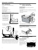
Dishwasher Installation STEP 3: REMOVE WOOD BASE, INSTALL LEVELING LEGS STEP 1: PREPARATION Locate the items in the installation package: 6FUHZV -XQFWLRQ ER[ FRYHU 'UDLQ KRVH DQG FODPS 0RXQWLQJ EUDFNHWV 7ULP SLHFHV RQ VRPH PRGHOV 'UDLQ KRVH KDQJHU 2ZQHU V 0DQXDO 3URGXFW VDPSOHV DQG RU FRXSRQV IMPORTANT – 'R QRW NLFN RȺ ZRRG EDVH Damage will occur. 0RYH WKH GLVKZDVKHU FORVH WR WKH LQVWDOODWLRQ ORFDWLRQ DQG OD\ it on its back.
Dishwasher Installation STEP 6: INSTALL 90° ELBOW :UDS D HOERZ ZLWK thread seal tape. 7KUHDG HOERZ :DWHU 9DOYH onto the water valve. Bracket 'R QRW RYHUWLJKWHQ elbow. Water valve bracket could bend or water valve fitting could break. Thread 3RVLWLRQ WKH HQG RI Seal the elbow to face the Tape rear of the dishwasher.
Dishwasher Installation STEP 10: SLIDE DISHWASHER THREE-FOURTHS OF THE WAY INTO CABINET IMPORTANT – Do not push against front panel with knees. Damage will occur. *UDVS WKH VLGHV RI WKH IURQW SDQHO DQG VOLGH GLVKZDVKHU LQWR the opening a few inches at a time. STEP 12: INSTALL MOUNTING BRACKETS You will need the mounting brackets and 2 #8 hex-head screws set aside in Step 1.
Dishwasher Installation STEP 13: PUSH DISHWASHER INTO FINAL POSITION Check the tub insulation blanket, if equipped, to be sure it is smoothly wrapped around the tub. It should not be “bunched up” and it must not interfere with the door springs. If the insulation is “bunched up” or interfering with the springs, straighten and recenter the blanket prior to sliding the dishwasher into its final position. 6OLGH WKH GLVKZDVKHU LQWR WKH ILQDO SRVLWLRQ E\ SXVKLQJ RQ WKH sides of the door panel.
Dishwasher Installation STEP 15: POSITION DISHWASHER, SECURE TO COUNTERTOP OR CABINET In this step you will need the 2 Phillips special head screws from the screws set aside in Step 1. The dishwasher must be secured to the countertop or the cabinet sides. When the underside of the countertop is wood, use Method 1. Use Method 2 when the underside of the countertop is made of a material, such as granite, that will not accept wood screws. IMPORTANT – Prevent door panel and control panel damage.
Dishwasher Installation STEP 17: CONNECT DRAIN LINE (Cont.) &RQQHFW GUDLQ OLQH WR DLU JDS ZDVWH WHH RU GLVSRVHU using the previously determined method. Secure hose with a screw-type clamp. Method 1 – Air gap with waste tee or disposer STEP 18: CONNECT POWER SUPPLY If a power cord with plug is already installed proceed to Step 19. WARNING: If house wiring is not 2-wire with ground, a ground must be provided by the installer.
Dishwasher Installation STEP 19: PRETEST CHECKLIST STEP 20: DISHWASHER WET TEST Review this list after installing your dishwasher to avoid charges for a service call that is not covered by your warranty. ■ Check to be sure power is OFF. ■ Turn on power supply or plug power cord into outlet, if equipped. ■ Open door and remove all foam and paper packaging. ■ Locate the Owner’s Manual set aside in Step 1. ■ Read the Owner’s Manual for operating instructions. ■ Check door opening and closing.
Dishwasher Installation STEP 21: POSITION SOUND BARRIER AND INSULATION (on some models) STEP 22: REPLACE TOEKICK 3ODFH WRHNLFN DJDLQVW WKH OHJV RI WKH GLVKZDVKHU Skip this step if the sound barrier is not assembled to the dishwasher.
Notes 14
Notes 15
SPECIFICATIONS SUBJECT TO CHANGE WITHOUT NOTICE GE Appliances General Electric Company Louisville, Kentucky 40225 GEAppliances.
Appareils ménagers GE Appliances Directives d’installation Lave-vaisselle encastré Pour toute question, composez le 1.800.561.3344 ou visitez notre site Web: www.electromenagersge.ca ARRÊT AVANT DE COMMENCER Veuillez lire attentivement toutes les directives qui suivent. IMPORTANT – Observez tous les codes et ordonnances en vigueur. Note à l’installateur – Veuillez laisser les présentes directives au consommateur pour l’inspecteur local.
Préparation pour l’installation PIÈCES FOURNIES DANS L’EMBALLAGE: ■ Couvercle de la boîte de jonction et vis à tête hexagonale n° 10 ■ Collier ■ Boyau de vidange (198 cm/78 po de long) ■ Support de tuyau de vidange) ■ 2 vis à tête hexagonale no 8-18 pour fixer les supports au cadre de la cuve du lave-vaisselle ■ 2 Boutons de bouchon ■ 2 Moulures latérales (certains modèles) ■ 2 supports de montage pour comptoirs ou armoires latérales en bois ■ 2 vis à tête spéciale Phillips n° 8-18 x 15,8 mm (5/8 po) pour f
Préparation pour l’installation PRÉPARATION DE L’OUVERTURE DANS LES ARMOIRES 87,6 cm ± 6,3 mm (34 1/2 po ± 1/4 po) du dessous du comptoir au plancher Figure A Le mur du fond doit être exempt de tuyaux ou de fils /H ODYH YDLVVHOOH GRLW rWUH LQVWDOOp GH IDoRQ j FH TXH OH ER\DX de vidange mesure au maximum 3.66 mètres (12 pieds) pour assurer une vidange adéquate. /H GHVVXV OHV F{WpV HW O·DUULqUH GX ODYH YDLVVHOOH GRLYHQW être complètement dissimulés à l’intérieur de l’ouverture.
Préparation pour l’installation PRÉPARATION DU CÂBLAGE ÉLECTRIQUE Autre emplacement possible pour la prise de courant AVERTISSEMENT: POUR VOTRE SÉCURITÉ PERSONNELLE: Enlevez le fusible ou déclenchez le disjoncteur au panneau de distribution principal avant de commencer l’installation.
Préparation pour l’installation PRÉPARATION DE L’ALIMENTATION EN EAU CHAUDE /D FRQGXLWH SHXW HQWUHU GX F{Wp JDXFKH GX F{Wp GURLW de l’arrière ou du plancher dans la partie ombrée indiquée dans la Figure F. /D FRQGXLWH SHXW SDVVHU SDU OH PrPH WURX TXH OH FkEOH électrique et le boyau de vidange, ou vous pouvez percer un trou supplémentaire de 3,8 cm (1-1/2 po) de diamètre pour le passage de la conduite d’eau.
Installation du lave-vaisselle ÉTAPE 1: PRÉPARATION 3UHQH] OHV SLqFHV IRXUQLHV GDQV O·HPEDOODJH HW PHWWH] OHV GH F{Wp (QVHPEOH GH YLV &RXYHUFOH GH OD ERvWH GH MRQFWLRQ %R\DX GH YLGDQJH HW FROOLHU 6XSSRUWV GH PRQWDJH 0RXOXUHV FHUWDLQV PRGqOHV &URFKHW SRXU ER\DX GH YLGDQJH 0DQXHO G·XWLOLVDWLRQ eFKDQWLOORQV HW RX ERQV ÉTAPE 2: VÉRIFICATION DE L’ÉQUILIBRE DE LA PORTE La porte se 6DQV HQOHYHU OD EDVH GH referme bois du lave-vaisselle, àl'intérieur YpUL¿H] O·pTXLOLEUH GH OD de 20° porte
Installation du lave-vaisselle ÉTAPE 5: INSTALLATION DU MATÉRIAU INSONORISANT (sur certains modèles) Passez à l'étape suivant si le lave-vaisselle n'est pas équipé de matériau insonorisant Relevez le matériau insonorisant et le ruban et fixez-le au panneau frontal à l'aide du ruban-cache. Ceci permettra de garder le matériau insonorisant relevé et de dégager la zone de travail pendant l'installation.
Installation du lave-vaisselle ÉTAPE 10: INSERTION AUX TROIS QUARTS DU LAVE-VAISSELLE DANS L’OUVERTURE IMPORTANT – Ne poussez pas sur le panneau avant avec vos genoux. Vous pourriez endommager l’appareil. 6DLVLVVH] OH SDQQHDX DYDQW GH O·DSSDUHLO SDU OHV F{WpV HW faites glisser le lave-vaisselle dans l’ouverture de quelques centimètres ou pouces à la fois.
Installation du lave-vaisselle ÉTAPE 13: INSTLLATION DU LAVE-VAISSELLE DANS SON EMPLACEMENT DÉFINITIF 9pULILH] O·LVRODQW GH OD FXYH V·LO \ D OLHX SRXU YRXV DVVXUHU qu’il enveloppe complètement la cuve. L’isolant ne doit pas «retrousser» ou entrer en contact avec les ressorts de la porte. Si l’isolant est «déplacé» ou entre en contact avec les ressorts, replacez-le correctement avant de faire glisser l’appareil dans son emplacement définitif.
Installation du lave-vaisselle ÉTAPE 15: FIXATION DU LAVE-VAISSELLE AUDESSOUS DU COMPTOIR OU AUX CÔTÉS DES ARMOIRES Au cours de cette étape, vous aurez besoin des deux vis à tête VSpFLDOH 3KLOOLSV PLVHV GH F{Wp j O·pWDSH Le lave-vaisselle doit être fixé au dessous du comptoir ou aux F{WpV GHV DUPRLUHV /RUVTXH OH GHVVRXV GX FRPSWRLU HVW HQ ERLV utilisez la méthode n° 1.
Installation du lave-vaisselle ÉTAPE 17: RACCORDEMENT DU BOYAU DE VIDANGE L’extrémité moulée du boyau de vidange est conçue pour s’installer sur l’orifice d’entrée d’un diamètre variant entre 15,8 mm (5/8 po) et 25,4 mm (1 po) de la coupure anti-refoulement, du raccord en T ou du broyeur à déchets. 0HVXUH] OH GLDPqWUH GH O·RUL¿FH G·HQWUpH &RXSH] OH UDFFRUG GX Ligne de coupe boyau de vidange à l’endroit indiqué, 15,8 mm (5/8 po) au besoin, pour qu’il soit bien DGDSWp j O·RUL¿FH d’entrée.
Installation du lave-vaisselle ÉTAPE 18: BRANCHEMENT DE L’ALIMENTATION ÉLECTRIQUE ÉTAPE 19: LISTE DE CONTRÔLE PRÉLIMINAIRE Si un cordon d’alimentation pourvu d’une fiche est déjà installé sur l’appareil, passez à l’étape 19. Passez en revue cette liste après l’installation de votre lave-vaisselle pour éviter des frais de réparation inutiles non couverts par votre garantie.
Installation du lave-vaisselle ÉTAPE 20: ESSAI DU LAVE-VAISSELLE AVEC DE L’EAU ■ Rétablissez l’alimentation électrique ou si l’appareil est doté d’un cordon d’alimentation, branchez-le dans la prise de courant murale. ■ Sélectionnez un cycle à exécuter et pressez la touche Start/ Reset (Démarrer/Réinitialiser). ■ Vérifiez que la porte est verrouillée. Le lave-vaisselle devrait démarrer. ■ Assurez-vous que le lave-vaisselle se remplit.
Installation du lave-vaisselle ÉTAPE 22: RÉINSTALLATION DU PANNEAU INFÉRIEUR $SSX\H] OH SDQQHDX LQIpULHXU FRQWUH OHV SLHGV GH QLYHOOHPHQW du lave-vaisselle. Panneau infé rieur Vis de fixation Figure CC $OLJQH] OH SDQQHDX LQIpULHXU SDU UDSSRUW DX EDV GH OD SRUWH et assurez-vous qu’il repose sur le plancher. ,QVpUH] HW VHUUH] OHV GHX[ YLV GH ¿[DWLRQ GX SDQQHDX LQIpULHXU Le panneau inférieur doit demeurer en contact avec le plancher.
Notes 15
LES SPÉCIFICATIONS PEUVENT ÊTRE MODIFIÉES SANS PRÉAVIS GE Appliances General Electric Company Louisville, Kentucky 40225 www.electromenagersge.