Installation Instructions Built-in Dishwasher If you have questions, call 800.GE.CARES(800.432.27371or visit our Website at: GEAppliances.com. In Canada, please call 1.800.561.3344 or visit www.geappliances.ca BEFORE YOU BEGIN Read these instructions carefully. IM PO RTA N T - completely IM PORTANT - The dishwasherMUST be installed to allow for future removal from the enclosure if service is and required. Observeallgoverningcodesand ordinances.
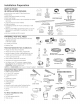
Installation Preparation PARTS SUPPLIED IN INSTALLATION ? PACKAGE: , Junction box cover and #10 hex-head screw , Hose clamp , Drain hose (approximately 78" long) Drain hose hanger 2 #8-18 hex head screws to secure brackets to washer tub frame @ #10 Hex-Head Junction Box Screw 1/2" long Junction Box Cover Hose Clamp #8 Hex-Head Mounting Bracket Screws Top Trim Piece (on some models) Side Trim Pieces 2 #8-18 x 5/8" Phillips special head screws, to secure dishwasher to underside of countertop or to
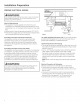
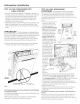
Installation Preparation PREPARE DISHWASHER ENCLOSURE kWARNING: To reducethe risk of electric shock,fire, or injuryto persons,the installer must ensurethat the dishwasheris completelyenclosed at the time of installation. 33-1/2" to 34-3/4" Underside of Countertop to Floor The dishwasher must be installed so that drain hose is no more than 12' in length for proper drainage. The dishwasher must be fully enclosed on the top, sides and back, and must not support any part of the enclosure.
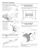
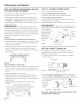
Installation Preparation PREPARE ELECTRICAL WIRING / AWARNING: _//_/_ I / '__ Receptacle Alternate Location I I \ \ FORPERSONAL SAFETY: Removehousefuse or open circuit breaker beforebeginning installation.Do not usean extensioncord or adapter plug with this appliance. Electrical Requirements , This appliance must be supplied with !20V, 60 Hz., and connected to an individual properly grounded branch circuit, protected by c] 15- or 20-ampere circuit breaker or time-delay fuse.
Installation Preparation PREPARE HOT WATER LINE NOTE:GE recommends copper tubing for the water line, but if you choose to use flexible hose, use GE'sW×28×326, flexible braided hose. . The water supply line (3/8" copper tubing or flexible braided hose) may enter from either side, rear or floor within the shaded area shown in Figure F. . The water supply line may pass through the same hole as the electrical cable and drain hose. Or,cut an additional 1-1/2" diameter hole to accommodate the water line.
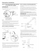
Dishwasher Installation STEP 1:PREPARATION STEP 3: REMOVE WOOD BASE, INSTALL LEVELING LEGS Locate the items in the installation package: , Screws Junction box cover Drain hose and clamp Mounting brackets Trim pieces (on some models) Drain hose hanger Owner's Manual Product samples and/or coupons IMPORTANT - Do not kickoffwood base! Damage will occur. Move the dishwasher close to the installation location and lay it on its back.
Dishwasher Installation STEP 6: REMOVE FLOOR PROTECT Squeeze connector at top to release snap feature , Disconnect leak sensor wire (on some models). Remove 2 screws from front of the Floor Protect with a 1A"driver. Rotate Floor Protect outward and lift out of the mounting tabs. Set aside for use in Step 22. STEP 9: POSITION WATER LINE AND HOUSE WIRING Position water supply line and house wiring on the floor of the opening to avoid interference with base of dishwasher and components under dishwasher.
Dishwasher Installation STEP 11: SLIDE DISHWASHER THREE-FOURTHS OF THE WAY INTO CABINET IM PORTANT - Donotpush against front panel with knees. Damage will occur. • Grasp the sides of the front panel and slide dishwasher into the opening a few inches at a time. STEP 13: INSTALL MOUNTING BRACKETS You will need the mounting brackets and 2 #8 hex-head screws set aside in Step !.
Dishwasher Installation STEP 14: PUSH DISHWASHER FINAL POSITION INTO IM PORTANT , Check the tub insulation blanket, if equipped, to be sure it is smoothly wrapped around the tub. It should not be "bunched up" and it must not interfere with the door springs. If the insulation is "bunched up" or interfering with the springs, straighten and recenter the blanket prior to sliding the dishwasher into its final position. . Slide the dishwasher into the final position by pushing on the sides of the door panel.
Dishwasher Installation STEP 16: POSITION DISHWASHER, TO COUNTERTOP OR CABINET SECURE STEP 17: CONNECT WATER SUPPLY Connect water supply line to 90 ° elbow. In this step you will need the 2 Phillips special head screws from the screws set aside in Step 1. If using a flexible braided hose connection: . Attach nut to 90° elbow using an adjustable wrench. The dishwasher must be secured to the countertop or the cabinet sides. When the underside of the countertop is wood, use Method 1.
Dishwasher Installation STEP 18: CONNECT DRAIN LINE (Cont.) . Connect drain line to air gap, waste tee or disposer using the previously determined method. Secure hose with a screw-type clamp. Method 1 - Air gap with waste tee or disposer STEP 19: CONNECT POWER SUPPLY Ifa power cord with plug is already installed proceed to Step 20. AWARNING: If housewiring isnot 2-wire with ground,a ground must be providedby the installer.
Dishwasher Installation STEP 20: PRETEST CHECKLIST STEP 21: DISHWASHER WET TEST Review this list after installing your dishwasher to avoid charges for a service call that is not covered by your ,Turn on power supply or plug power cord into outlet, if equipped. wa r ra nty. . Check to be sure power is OFF. , Open door and remove all foam and paper packaging. , Locate the Owner's Manual set aside in Step 1. , Read the Owner's Manual for operating instructions.
Dishwasher Installation , On models so equipped, remove the masking tape from the sound barrier and door front. Position the sound barrier over STEP 23: POSITION INSULATION, PRETOEKICK, AND SOUND BARRIER Ion some models) the insulation. Sound Skip this step if the sound insulation package is not supplied with the dishwasher. . Locate the sound insulation package and pre-toekick packages inside the dishwasher. , Stand the partSDishwasherUpright as......_._jshown.
Notes 14
Notes 15
SPECIFICATIONS SUBJECT TO CHANGE WITHOUT NOTICE GEAppliances General Electric Company Louisville, Kentucky/40225 GEAppliances.
Appareils m@nagers Directives d'instailation Lave-vaisselle encastr@ Pour toute question, composez le 1.800.561.3344 ou visitez notre site Web: www.electromenagersge.ca AVANT DE COMMENCER IM PORTANT Veuillez lira attentivement toutes les directives mani_re 6 ce qu'il puisse _tre sorti de son emplacement si des r@arations sont n6cessaires. qui suivent. IM PO RTANT - Observez touslescodes et ordonnances en vigueur. .
Pr6paration pour I'installation PIECESFOURNIES DANS UEMBALLAGE: . Couvercle de la boTte dejonction et vis 6 t6te hexagonale n° 10 . Collier , Boyau de vidange (198 cm/78 po de long) , Support de tuyau de vidange , 2 Vis 6 t_te hexagonale no 8-18 pour fixer les supports au cadre de la cure du lave-vaisselle , 2 Boutons de bouchon , 2 Houlures lat@ales , 1 Garniture sup6rieure (certains modales) .
Preparation pour I'installation PRI_PARATION DE L'OUVERTURE DANS LES ARMOIRES AVERTISSEMENT : Pour r_duireles risquesde choc _lectrique,d'incendieou de blessures,I'installateurdoit s'assurerque le lave-vaisselleest compl_tementencastr_au moment de I'installation. Le lave-vaisselle doit _tre install6 de faqon 6 ce que le boyau de vidange mesure au maximum :3.66 m_tres (12 pieds) pour assurer une vidange ad6quate.
Preparation pour I'installation PRE PARATION DU C#,BLAGE I LECTRIQUE _'/ / AVERTISSEMENT : POURVOTRESECURITE PERSONNELLE: Enlevezle fusible ou d@clenchezle disjoncteurau panneau de distribution principal avant de commencer I'installation.N'utilisezpas une rallonge @lectriqueou un adaptateur de fiche avec cet appareil. _ 46 cm (18 po) -- 46 cm i÷ (18 po) I /1÷'- Alimentotion @lectrique .
Preparation pour I'installation PRI PARATION DE L'ALIMENTATION EAU CHAUDE EN REMARQUE:GE recommande I'utilisation d'un tuyau en cuivre pour la conduite d'alimentation en eau, mais vous pouvez choisir un boyau flexible tress6 no W×28×326 de GE. . La conduite d'alimentation en eau (tuyau de cuivre de 9,5 mm [13/8po] ou boyau flexible tress6) peut entrer du c6t6 gauche, du c6t_ droit, de I'arri_re ou du plancher dans la partie ombr6e indiqu6e dans la Figure F. .
Installation du lave-vaisselle ETAPE 1: PREPARATION Prenezles pisces fournies dans I'emballage et mettez-les de cStS: , Ensemble de vis Couvercle de la boTtedejonction Boyau de vidange et collier Supports de montage Moulures (certains modSles) Crochet pour boyau de vidange Manuel d'utilisation Echantillons et(ou) bons IMPORTANT - Ne frappez pas sur labase de bois pour l'enlever! Vous endommagerez ainsi l'appareil.
Installation du lave-vaisselle I_TAPE 5: INSTALLATION DU MATI_RIAU INSONORISANT (sur certaJns modules) Passez 6 l'_tape suJvant si le lave-vaisselle n'est pas _quip_ de mat_riau insonorisant Relevez le mat@iau insonorisant et le ruban et fixez-le au panneau frontal 6 I'aide du ruban-cache. Ceci permettra de garder le mat@riau insonorisant relev6 et de d6gager la zone de travail pendant I'installation.
Installation du lave-vaisselle I_TAPE 11: INSERTION AU× TROIS LAVE-VAISSELLE DANS DU I_TAPE 13: INSTALLATION L'OUVERTURE DE MONTAGE QUARTS DES SUPPORTS - Ne poussez pas surle panneau avant avec vos genoux. Vous pourriez endommager l'appareil. IMPORTANT Vous aurez besoin des supports de montage et de deux (2)vis 6 t@tehexagonale no 8 raises de c6t6 6 1'6tape 1. .
installation du lave-vaisselle I TAPE 14: INSTLLATION DU LAVEVAISSELLE DANS SON EMPLACEMENT DI FINITIF . V6rifiez I'isolant de la cuve, s'il y a lieu, pour vous assurer qu'il enveloppe compl6tement la cuve. L'isolant ne doit pas <> ou entrer en contact avec les ressorts de la porte. Si I'isolant est <> ou entre en contact avec les ressorts, replacez-le correctement event de faire glisser I'appareil dens son emplacement d6finitif. .
Installation du lave-vaisselle I TAPE 16: FIXATION DU LAVE-VAISSELLE AUDESSOUS DU COMPTOIR OU AUX C6TI S DES ARMOIRES Au cours de cette @ape, vous aurez besoin des deu× vis 6 t6te sp6ciale Phillips mises de c6t6 6 1'6tape1. Le lave-vaisselle dolt 6tre fix6 au dessous du comptoir ou au× c6t6s des armoires. Lorsque le dessous du comptoir est en bois, utilisez la m@thade n° 1.
Installation du lave-vaisselle ETAPE 18: RACCORDEMENT DU BOYAU DE VIDANGE L'extr6mit6 moul6e du boyau de vidange est conque pour slnstaller sur I'orificed'entr6e d'un diam6tre variant entre 15,8 mm (5/8 po/et 25,4 mm (1 po/de la coupure antPrefoulement, du raccord en T ou du broyeur 6 d6chets. . Mesurezle diam6tre de I'orificed'entr6e. . Coupez le raccord du Ligne de coupe boyau de vidange 6 I'endroit indiqu6, ,_ lS,8 mm IS/8po) au besoin,pour qull soit bien adapt6 6 I'orifice I__l d'entr6e. .
Installation du lave-vaisselle I_TAPE 19: BRANCHEMENT L'ALIMENTATION DE I_LECTRIQUE Si un cordon d'alimentation pourvu d'une fiche est d_j6 install_ sur l'appareil, passez 6 l'_tape 20. A AVERTISSEMENT : I_TAPE 20: LISTE DE CONTROLE PRI_LIMINAIRE Passez en revue cette liste apr_s I'installation de votre lave-vaisselle pour _viter des frais de r_paration inutiles non couverts par votre garantie. . Assurez-vous que le courant 61ectrique est coup6 6 la source.
Installation du lave-vaisselle I_TAPE 21: ESSAI DU LAVE-VAISSELLE AVEC DE L'EAU I_TAPE 22: INSTALLATION DU PROTI_GE- , R6tablissez I'alimentation 61ectrique ou si I'appareil est dot6 d'un cordon d'alimentation, branchez-le dans la prise de courant murale. , Faites glisser le prot_ge-plancher sous le lave-vaisselle. Angle the rear back edge of the Floor Protect upwards to engage mounting tabs. , Soulevez le devant du plateau et s_curisez avec les 2 vis.
Installation du lave-vaisselle I_TAPE 23: Installation du mat_riau isolant, du panneau inf_rieur pr_alable et du mat_riau insonorisant.{sur certains modules} Sautez cette _tape sJ votre lave-vaisselle d'ensemble d'insonorisation. ne comprend pas . Situez I'ensemble d'insonorisation et I'ensemble du panneau inf@ieur pr6alable 6 I'int@ieur du lave-vaisselle. . Rep@ez I'emballage du mat@iau isolant 6 I'int@ieur du lavevaisselle.
Notes 15
LES SPECIFICATIONS PEUVENT ETRE MODIFII_ES SANS PREAVIS GEAppliances General Electric Company Louisville, Kentucky/40225 www.electromenagersge.
Instrucciones de Instalaci6n LavavajillasIncorporado Ante cualquier dude, comuni.cluese al800.GE.CARES (800.432.2737) o visite nuestro.sitio web en: GEAppliances.com. En Canada, comuniquese al 1.800.561.3344 o visite www.geappliances.ca. ANTES DE COMENZAR Lea estas instrucciones en su totalidad y atentamente. IM PORTANTE - Cumpla con todos los c6digos y ordenanzas gubernamentales , Note pare el Instalador - AsegOrese de entregar estas instrucciones al consumidor y al inspector local.
Preparaci6n de la Instalaci6n PIEZAS SUMINISTRADAS ? EN EL PAQUETE DE INSTALACI6N: .Tapa de la caja de empalmes y tornillo de cabeza hexagonal n o 10 . Abrazadera de la manguera . iVlanguera de desag0e (aprox. 78" de Iongitud) . Sostenedor de la manguera de desag0e .2 Tornillos de cabeza hexagonal no 8-18 para asegurar lossoportes de la estructura de la tuberia de la lavadora .1 Pieza del borde superior (algunos modelos) .2 Piezas del borde lateral .
Preparaci6n de la Instalaci6n PREPARE EL AMURADO DEL LAVAVAJILLAS A ADVERTENCIA: Para reducir el riesgo de descarga el6ctrica, incendio o lesiones a personas, el instalador debe asegurarse de que el lavaplatos est6 completamente cerrado en el momento de la instalaci6n. Elarea de esta pared deber6 estar libre 33-1/2" a 343/4" en la parte inferior desde la mesada al El lavavajillas se deber_ instalar de forma tal que la manguera de desag0e no tenga mc_sde 12" de Iontigud para un desag0e adecuado.
Preparaa6n de la Instalaci6n PREPARACI6N DEL CABLEADO ELI_CTRICO ,_ i ADVERTENCIA: PARASEGURIDADPERSONAL:Quite el fusible o abra el interruptor de circuitos antes de comenzar la instalaci6n. No utilice un cable de extensi6n o un enchufe adaptador con este artefacto.
Preparaci6n de la Instalaci6n PREPARACI6N CALIENTE DE LA LJNEA DE AGUA A PRECAUCI6N: NOTA:GE recomienda el uso de tuberias de cobre para la linea de agua, pero si decide usar una manguera flexible, use la manguera trenzada flexible W×28×326 de GE. , La linea de suministro de agua (la tuber[a de cobre de 3/8"o la manguera trenzada flexible) podr@ingresar desde cualquiera de los laterales, desde la parte trasera o desde el piso dentro del @teasombreada que se muestra en la Figura F.
Instalaci6n del Lavavajillas PASO 1:PREPARACI6N PASO 3: RETIRE LA BASE DE MADERA, INSTALE LAS PATAS NIVELADORAS Ubique los items en el paquete de instalaci6n: , Tornillos .Tapa de la caja de empalmes . ilanguera de desag_e y clavUa , Soportes de montaje , Pieza de los bordes (en algunos modelos . Gancho de la manguera de desag0e . Manual del propietario .
Instalaci6n del Lavavajillas PASO 6: RETIRE LA PROTECCI6N DEL PISO • Desconecte el cable del sensor de Apriete el conector en la parte superior para liberar goteo (en olgunos modelos). la funci6n de ajuste. • Retire los 2 tornillos del frente de lu Protecci6n peru Pisos con un destornilludor delA ''. • Gire lu protecci6n del piso huciu afueru y levonte lu mismo de los lengQetus de montaje. \ • Deje o un costado pore use en el Paso 22.
Instalaci6n delLavavdillas PASO 11: DESLICE EL LAVAVAJILLAS TRES CUARTOS DEL RECORRIDO DENTRO DEL GABINETE IMPORTANTE -Nolo empuje contra elpanel frontal con los rodillas. Se producir6n daflos. • Tome los laterales del panel frontal y deslice el lavavajillas en la abertura de a pocas pulgadas par vez. PASO 13: INSTALE LOS SOPORTES DE MONTAJE Necesitar6 los soportes de montaje y los 2 tornillos hexagonales no 8 que separ6 en el Paso 1.
Instalaci6n dei Lavavajillas PASO 11.4:COLOQUE EL LAVAVAJILLAS EN SU POSICION FINAL Controle que la manta aislante, si est6 presente, est6 envuelta de forma pareja alrededor de la tuber[a. No deber[a estar "amontonada" y no debe interferir con los resortes de la puerta. Si el aislante est6 "amontonado" o interfiere con los resortes, alargue y vuelva a centrar la manta antes de deslizar el lavavajillas hasta su posici6n final.
Instalaci6n dei Lavavajillas PASO 15: NIVELE EL LAVAVAJILLAS I MPORTANTE - Ellavavajillas deberc_ester nivelado pare un funcionamiento apropiado del estante de los platos, el rendimiento del lavado y el funcionamiento de la puerta. El lavavajillas deber@estar i i nivelado de izquierda f \\ \ a derecha y del frente / \ a la parte trasera.
Instalaci6n del Lavavajillas PASO 16: POSICIONE EL LAVAVAJILLAS, ASEGURE EL MISMO A LA MESADA O EL GABINETE En este paso, necesitar6 los 2 tornillos con cabeza especial Phillips, de los tornillos qua separ6 en el Paso !. El lavavajillas debar6 estar asegurado a la mesada o a los costados del gabinete. Cuando el lado inferior de la mesada sea de madera, use el M_todo Z. Use el M_todo 2 cuando el lado inferior de la mesada est6 hecho de un material qua no acepte tornillos de madera, tal coma el granito.
Instalaci6n dei Lavavajillas PASO 18: CONECTE LA LiNEA DE DESAGUE (Cont.) PASO 19: CONECTE EL SUMINISTRO CORRIENTE , Conecte la Ifnea de desagC_ea la brecha de aire, la T de desechos o el eliminador de desechos, usando el m6todo determinado previamente. Asegure la manguera con una clavija tipo tornillo. Si un cable de corriente M_todo 1 - Brecha de aire con T de desechos de desechos o el eliminador con un enchufe DE ya est6 instalado, proceda al Paso 20.
Instalaci6n del Lavavajillas PASO 20: LISTA DE CONTROL DE EVALUACI6N PREVIA PASO 21: PRUEBA DE MOJADO DEL LAVAVAJ ILLAS Revise esta lista luego de instalar el lavavajillas, a fin de evitar cargos pot llamadas al servicio t_cnico, las cuales no est_n cubJertas por su garantia. . Active la corriente y enchufe el cable de corriente en el tomacorriente, si est@equipado de este modo. AsegOrese de que el encendido est6 en OFF (Apagado). Abra la puerta y retire toda la gomaespuma y el papel de embalaje.
Instalaci6n dei Lavavajillas PASO 22: REEMPLACE LA PROTECCI6N PISOS (en algunos PARA • Ubique la caja de control. Caja de Control modelos) , Deslice la Protecci6n para Pisos deba]o del lavavajillas. , Coloque en Bngulo el extremo inferior de la Protecci6n para Pisos hacia arriba, para adherir las leng_etas de montaje. , Levante el frente de la bandeja de goteo y asegure la misma con 2 tornillos. , Conecte el conector del sensor de goteo al sensor de goteo. i y _..
Instalaci6n del Lavavajillas STEP 24: PASO 24: REEMPLACE EL Z6CALO . Coloque el z6calo contra el pre-z6calo (en algunos modelos) y las patas del lavavajillas. Figura AH agarre . Alinee el z6calo con el extremo inferior y asegL]rese de que est6 contra el piso. . Inserte y ajuste los 2 tornillos de agarre al z6calo. Elz6calo deber_ permanecer en contacto con el piso. .
ESPECIFICACIONES SUJETAS A CAPIBIOS SIN AVISO PREVIO GEAppliances General Electric Company Louisville, Kentucky/40225 GEAppliances.