Installation Instructions ZIC360N RH,ZIC360N LH, ZICS360N RH,ZICS360N LH Built-In Bottom-Freezer Refrigerators Design 6uide With Installation Instructions Monogram:
Safety Information BEFORE YOU BEGIN Skill Level requires Read these instructions completely • IMPORTANT for h)cal inspector's and ordinances. • Note instructions • Note with with use. to Installer Owner carefully. all goxerning the s Manual for flmue reference. appareil (hilt <_ Mise &tre correctement _'l la terre If you receixed a damaged immediatelx contact xom" du See mis _'l la terre. r(_frig_ratem" _>, I)age, 9. refrigerator, you dealer or builder.
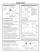
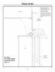
Design Guide THE INSTALLATION DIMENSIONS SPACE 35-I/2" FinishedWidth .to.t width/llg mustbe /11 The linished _1_ / 84-1/ 35" CaseWidth 25-3/4"Framed Models 25-3/4"Stainless SteelModels CaseOept,, _ Shippingheight.The 2-8/1B'' _T AND CLEARANCES ,, Im :8 --'_ Wal,View maxL 10 ]] 83-1/2" min ]L_24" CutoutDepth Finished _83-1'2"1 _ ] From _'84" I Floorto TopFrame to refrigerator fit intomin.to a cutoutthat can 84-1/2" be adjusted is 83-1/2" max. height.
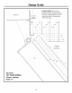
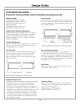
Design Guide FramelessCabinets: The case trim Refrigerator 23-7/8"From Rearof Refrigerator overlaps cabinets at the top and sides. Therefore, frameless cabinets may require filler strips to prevent interference with cabinet door swing. The opening must allow for filler strips.
Design Guide FramelessCabinets: The case trim overlaps cabinets atthe top and sides. Therefore, frameless cabinets may require filler strips to prevent interference with cabinet door swing. The opening must allow for filler strips. Refrigerator CaseTrim 23-7/8" FromRearof Refrigerator 1/4" ..... _ .... _ i -- t-- i i -- ' -- i.... i i _ ' .... t .... .... 112 ,,LiL :: i i i . ................... 1 " I ',:'::'_--I-1 i ell --'_........... , t .... _=t,--7-1--t .............
Design Guide CUSTOMIZATION Framed Models BASICS: Or Overlay Panels, Custom Handles Available RH (right-handed I,H (lett-handed Kits Overlay panels You may also choose to install custom overlay panels fl'om your cabinet manufacturer.
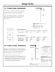
Design Guide 1/4" FRAMED PANEL DIMENSIONS Door If you choose to install framed panels, they must be cut to tile dimensions shown. Tile panels will slide into tile frame on tile door, drawer and ,rille If tile fits with custom loosely panel in tile a piece improve is less door of filler the than fi'ame, material 1/4" thick it can and be backed or fi_am tape if it up to fit. IMPORTANTNOTE:Maximum total panel weight: • Freshfood door panel-58 Ibs. • Freezer drawer panel- 28 Ibs.
Design Guide SIDE PANELS ZUG2 GRILLE PANEL DIMENSIONS Side panels must be used whenever the sides of the refrigerator will be exposed. The 1/4" side panels will slip into the side case trim. Secure the panels to the refrigerator with stick-on hook and loop fastener strips. Order the side panels fl'om the cabinet The ZUG2 installation I11[I n 11{;I tmified grille panel kit provides for the of a framed or o_erlay grille panel. A [ ct t II'eI'.
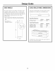
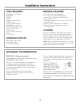
Installation Instructions TOOLS REQUIRED MATERIALS • • • • Tinsnips to cut banding Stepladder Bucket i,evel • 35" long 2x4 fl_r Anti-Tip support • 1/4" COl)per water line tubing or GE SmartConnecg" Refrigerator Tubing kits • X_'ater sh ut-ofl wflve • • • • • • Appliance Hand T_uck Tubing cutter 7/16" open-end wrench #9 Phillips screwdriver Drill and ai)propriate bits 5/]6", 7/16" socket • C/IStOIll panels tot fl'esh tood door, fl'eezer and grille panel • Screws to secure refrigerator to cabinetry:
Installation [STEP 1] REMOVE Instructions CAUTION: Refrigerator is much • Remoxe J PACKAGING hea, ier at the ATTEMPT TO ROI,I, UNIT OFF SKID. est pl.s Remove Tie-Downs hmrd en haut qu'en bas. I1 taut 6tre prudent lots des d@lacements. Si un diable est utilis& il taut soulexer le r_frig&'ateur stu" le c6t_ seulement. • Careflflly cut banding relilove otKer carton. / PRUDENCE:ICNE FAUT PAS ESSAYER DE FAIRE ROUI,ER I,E Rt_FI)d Gt_RATEUI). POUR at the top and bottom, I/ENI,EVER PA1,ETTE.
Installation Instructions [STEP 21(continued} I STEP 41 INSTALL ANTI-TIP BRACKETS WARNING: ANTI-TIP • Turn on the main water supply and flush debris. Run about a quml ot water through the robing into a bucket. Shut off water supply at the shut-offvalve. PRECAUTIONS The refiJgerator is top-heavy and must be secured to prexent the possibility of tipping fiwward. NOTE: Saddle type shut-off \;flves are included in many wamr supply kits.
Installation Instructions [STEP 6] SECURE REFRIGERATOR TO CABINETRY [STEP 5] LEVEL REFRIGERATOR All models have supported by leveling a_!justable wheels. of the leveling. legs, Both The rear the are front is is supported by fl'om the fl'ont tm'n the accessible X4henexer possible, perfl_m_ this step for anti-tip secm'ity, or when anti-tip brackets cannot be used. The refrigerator must be secured to prevent tipping. refl'igerator.
Installation [STEP 7] ADJUST Instructions DOOR SWING [STEP 81 INSTALL GRILLE PANEL NOTE: This refiigerator has a 2-position door stop. When space does not allow the door to swing open fldlv to 130 °, you may change the door swing to a 90 ° opening. Skip this step if door opening is satisfactory for your installation situation. • Raise the grill door stop and reinstall to stop position. I I Loosen Side Trim _, Screw • i,ift the grille panel to access the wire cover trim.
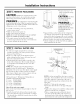
Installation I STEP 91 INSTALL FRAMED Instructions PANELS Handle Trim j Right hmad models shown. for left hand models. Use the same IF YOU ARE INSTALLING GO TO STEP 9A. OVERLAY instructions PANELS, DoorTrim Refrigerator Door UseFrontHoles to SecureTrim Standardsuppliedhandleshown in 1/4" panelposition. UseRearHoles to SecureHandle Install door and drawer panels: • Open door to 90 °. Remove the 4 Phillips fl'om the door handle. • Remove handle. Retain all screws.
Installation Instructions [STEP 9A] INSTALL OVERLAY PANELS Right hand models shown. Use the same instructions for left hm_d models. DoorTrim Handle Trim Refrigerator Door Move Forward For3/4" Panel - Use Front Holes to Secure Handle UseRearHoles to SecureTrim Suppliedhandleshown in the overlaypanelposition. Install door and drawer panels: • Open door to 90 °. Relnove the 4 Phillips ti'om the door handle. • Remove handle. P,emin all screws. • Remove 4 screws Retain screws.
Installation [STEP 10]CONNECT Instructions WATER SUPPLY I STEP 11] CONNECT POWER • Check to be sm'e tile power the receptacle. L[ cord is phlgged into Grille ]1! Raise Panel_] "N 4 :L. Electrical Outlet • Check to make opening are • i,ocate and bring tubing to the fl'ont of the cabinet. • Turn the water oil to flush debris frmn line. Run about a quart of water then s hut off wa te r.
Installation Instructions I STEP 131 INSTALL TOEKICK • I,ocate the the side provided, supplied of the toekick (shipped refl'igerator), a_!iust Install to desired height taped with and to 2 screws tighten screws, • A custom toekick complement supplied and vent the toekick holes, can be installed to match surrounding cabinetry, as a template to cut or Llse the out the notch SuppliedToekick 1/4" or Thicker Toekick Importm_t: unobstructed refl'igerator The xented toekick f
Notes 18
Notes 19
NOTE:While performing installations described in this book, safety glasses or goggles should be worn. t'_n"Mo_wg'r,m °° Iocnl ._vic_, ht your (m_,, c(lfl l. 800.444. 1845. NOTE: Pl-o(ltlc[ iln[)l-()'¢( mt_lll (;en(:r_d Ele(tri(:. Therefor(, sl)(_tifi(alions ar(_ sul)je(t is _ contimfing ,:m,:l( ;avov ;_t mar(:rials, ;q)l)(m-an(t and to (hang(: v.illlotll noli(t. Monogram: Pub.No. 49-60136-2 Dwg.No.