g GEH–6505A POWER LEADER™ Ethernet Gateway User’s Guide
GEH–6505 WARNINGS, CAUTIONS, AND NOTES AS USED IN THIS PUBLICATION WARNINGS Warning notices are used in this publication to emphasize that hazardous voltages, currents, or other conditions that could cause personal injury exist in this equipment or may be associated with its use. Warning notices are also used for situations in which inattention or lack of equipment knowledge could cause either personal injury or damage to equipment.
POWER LEADER™ Ethernet Gateway Table of Contents Chapter 1 – Introduction ........................................................................................... 1 1–1 Overview .................................................................................................................................. 1 1–2 Physical Description ............................................................................................................... 2 1-3 Operational Description...............................
POWER LEADER™ Ethernet Gateway Table of Contents List of Figures Figure 1. POWER LEADER Ethernet Gateway. ............................................................................................ 1 Figure 2. Typical use of Ethernet Gateway. ................................................................................................... 2 Figure 3. Front view of Ethernet Gateway, showing dimensions. ................................................................ 2 Figure 4.
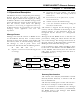
POWER LEADER™ Ethernet Gateway Chapter 1 – Introduction Chapter 1 – Introduction 1–1 Overview The GE POWER LEADER™ Ethernet Gateway (catalog number PLENETG01), shown in Figure 1, is a microprocessor-based device that connects one to four RS485-based Modbus Remote Terminal Unit (RTU) networks to an industry-standard, highspeed Ethernet network. Up to 31 Modbus RTU devices can be connected to each of the Modbus RTU networks.
POWER LEADER™ Ethernet Gateway Chapter 1 – Introduction Ho st P MC S Ot her PC Ot her PC Et her net Ethernet Gateway RS485 Modbus RTU PL C 90/ 30 Mul ti l in 56 5 RS485 Modbus RT U EPM 37 2 0 EP M 37 10 Mo db u s Concentr ator Mul ti l in 269+ PLC 90/ 70 Spect r a E CM PL E PM commnet devi ces POWE R LE ADE R Met er MVT - P M Tri p Unit Figure 2. Typical use of Ethernet Gateway. 1–2 Physical Description many as 31 Modbus devices each and up to 247 Modbus addresses each.
POWER LEADER™ Ethernet Gateway Chapter 1 – Introduction 1-3 Operational Description The Ethernet Gateway transparently passes message between the host and devices attached to the Gateway. Figure 5 illustrates the stripping or adding of Ethernet headers to the Modbus messages. This section describes the nature of these messages and how the Gateway routes them.
POWER LEADER™ Ethernet Gateway Chapter 1 – Introduction 1–4 Specifications 1–6 Terminology The specifications of the Ethernet Gateway are listed in Table 2. Following are definitions of some of the terms used in this document. Parameter Value Control power 90–132 Vac or 180–264 Vac, 47–63 Hz; autoranging POWER LEADER – The GE family of comprehensive power management devices and system software used to minimize downtime and overall power cost. PMCS – Power Management Control System software.
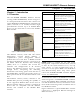
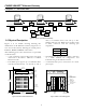
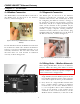
POWER LEADER™ Ethernet Gateway Chapter 2 – Installation Chapter 2 – Installation 2–1 Mounting The Ethernet Gateway may be mounted on a horizontal surface or on a wall, preferably inside an enclosure or switchgear lineup. The Gateway should be mounted so that it is spaced from enclosure walls or from other components in the enclosure.
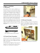
POWER LEADER™ Ethernet Gateway Chapter 2 – Installation 2–4 Modbus Connection 2–5 Diagnostic Connection The Modbus RTU networks should be connected to the RS485 ports on the back of the Ethernet Gateway, as shown in Figure 9. The RS232 port on the back of the Ethernet Gateway is provided for connection of a dumb terminal to the Gateway. The terminal may be used for configuring the Ethernet Gateway’s settings or for diagnostic purposes.
POWER LEADER™ Ethernet Gateway Chapter 2 – Installation devices. To the Modbus network, the commnet devices appear as valid Modbus addresses. manual) to record the devices attached to each network and verify that each device on each network has a unique address. To provide seamless integration of commnetcompatible devices into the Modbus RTU network, the Concentrator directly maps commnet addresses to equivalent Modbus addresses.
POWER LEADER™ Ethernet Gateway Chapter 3 – Configuration Chapter 3 – Configuration The Ethernet Gateway needs to be properly configured to communicate with your RS485 networks. Two items are critical to proper performance of your Gateway: the Gateway’s Ethernet address and the RS485 port communication settings. The Gateway’s Ethernet address should be set so that the host software will know how to address messages to the Gateway.
POWER LEADER™ Ethernet Gateway Chapter 3 – Configuration 3–2 Ethernet Gateway IP Address Enter the setting number you want to change, then press . Ethernet Gateway’s IP address must be properly set for it to receive messages sent by the host software. Consult your LAN personnel or system NOTE: The lower portion of the Configuration Menu is administrator for assistance in selecting the correct labeled Advanced Options. These options are for use IP address.
POWER LEADER™ Ethernet Gateway Chapter 3 – Configuration 3–4 Message Monitoring Option Number: Valid Entries at Prompt: 1 = RS485 Port 1 0 = 1200 baud 4 = 19200 baud 3 = RS485 Port 2 1 = 2400 baud 5 = 38400 baud 5 = RS485 Port 3 2 = 4800 baud 6 = 57600 baud 7 = RS485 Port 4 3 = 9600 baud 2 = RS485 Port 1 Data Bits: 0 = 7 data bits 1 = 8 data bits Stop Bits: 0 = 1 stop bit 1 = 2 stop bits Parity: 0 = None 1 = Even 2 = Odd 4 = RS485 Port 2 6 = RS485 Port 3 8 = RS485 Port 4 For diagnostic
POWER LEADER™ Ethernet Gateway Chapter 3 – Configuration 3–6 Gateway Diagnostics Enter the port to be tested: 1, 2, 3, or 4. The following message displays: Selecting menu item 11 exits the Gateway software and runs the Gateway diagnostics program. The Gateway Diagnostics menu shown in Figure 14 is displayed on the terminal. (where X is the port being tested). If the loop-back is successful, the following message will be displayed: (where Y is the loop-back port).
POWER LEADER™ Ethernet Gateway Chapter 3 – Configuration Network Test – FACTORY USE ONLY NOTE: A client program may be requested from GE to run on the host when performing the network test. The client attempts to establish a connection to a server (the Gateway) with the specified IP address, subnet mask and port number.
POWER LEADER™ Ethernet Gateway Chapter 4 – Operation Chapter 4 – Operation The Ethernet Gateway, once properly configured, requires no user intervention for operation. During normal operation, the Ethernet Gateway passes messages to and from the attached Modbus devices and translates these messages between the Ethernet and Modbus RTU protocols.
POWER LEADER™ Ethernet Gateway Chapter 5 – Errors and Diagnostic Messages Chapter 5 – Diagnostic Messages and Errors 5–1 Monitor Mode 5–2 Processing Error Messages The Ethernet Gateway can be set to send diagnostic Table 7 gives error messages that may be generated messages to the RS232 port to be displayed on a by the Gateway and displayed at the PMCS host. terminal (see Chapter 3).
POWER LEADER™ Ethernet Gateway Chapter 6 – Troubleshooting Guide Chapter 6 – Troubleshooting Guide The following guide is provided for troubleshooting and isolating common problems. It does not cover every possible condition. Contact the ED&C Customer Support Center at 800-843-3742 if the problem is not resolved by these procedures. Symptom 1. No response at either host PC or dumb terminal from the Ethernet Gateway. Possible Cause Lack of power.
POWER LEADER™ Ethernet Gateway Configuration Worksheets RS485 Port Configuration Worksheets Use the following worksheets to record the devices attached to the Ethernet Gateway for reference and troubleshooting. Record the Ethernet Gateway’s Ethernet address on the first page only, then fill in the information on the Modbus devices attached to each network: device type and physical location, and the Modbus address assigned to it.
POWER LEADER™ Ethernet Gateway Configuration Worksheets RS485 Port 2 Worksheet Baud Rate for RS485 Port 2 Modbus Network Device Number 2 1 2 2 2 3 2 2 2 2 2 2 2 2 2 2 2 4 5 6 7 8 9 10 11 12 13 14 2 2 2 15 16 17 2 2 2 2 2 2 2 18 19 20 21 22 23 24 2 2 25 26 2 2 2 27 28 29 2 2 30 31 Device Type & Physical Location / Notes 17 Modbus Address
POWER LEADER™ Ethernet Gateway Configuration Worksheets RS485 Port 3 Worksheet Baud Rate for RS485 Port 3 Modbus Network Device Number 3 1 3 3 2 3 3 3 3 3 3 3 3 3 3 3 3 4 5 6 7 8 9 10 11 12 13 14 3 3 3 15 16 17 3 3 3 3 3 3 3 18 19 20 21 22 23 24 3 3 25 26 3 3 3 27 28 29 3 3 30 31 Device Type & Physical Location / Notes 18 Modbus Address
POWER LEADER™ Ethernet Gateway Configuration Worksheets RS485 Port 4 Worksheet Baud Rate for RS485 Port 4 Modbus Network Device Number 4 1 4 4 2 3 4 4 4 4 4 4 4 4 4 4 4 4 5 6 7 8 9 10 11 12 13 14 4 4 4 15 16 17 4 4 4 4 4 4 4 18 19 20 21 22 23 24 4 4 25 26 4 4 4 27 28 29 4 4 30 31 Device Type & Physical Location / Notes 19 Modbus Address
g GE Electrical Distribution & Control General Electric Company 41 Woodford Ave.