
- General Electric Computer Accessories User Manual

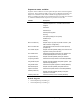
Table Of Contents
- Safety Symbol Legend
- Chapter 1 Overview
- Chapter 2 Faults and Troubleshooting
- Chapter 3 Paramters/Functions
- Introduction
- Diagnostic and Utility Functions
- Drive Configuration Functions
- General Setup Functions
- I/O Functions
- LAN Functions
- Motor Control Functions
- Protective Functions
- Custom User Faults
- DC Link Protection
- Ground Fault Protection (Fast)
- Hardware Fault Strings
- Heatsink Thermal Protection
- Line-Line Voltage Protection
- Motor Overtemperature Detection
- Phase Current Protection
- Timed Overcurrent Detection
- Transformer Overtemperature Detection
- Motor Ground Protection
- Phase Imbalance Monitor
- Line Monitor
- Phase Lock Loop
- Sequencer Functions
- Speed Reference Functions
- Speed/Torque Control Functions
- System Data Parameters
- Chapter 4 Wizards
- Introduction
- Introduction 4-1
- DAC Setup
- Drive Commissioning
- Drive Commissioning: Overview
- Drive Commissioning: Intelligent Part Number
- Drive Commissioning: Drive Units
- Drive Commissioning: AC Source Selection
- Drive Commissioning: Motor Nameplate Data
- Drive Commissioning: Motor Crossover Voltage
- Drive Commissioning: Motor Protection Class
- Drive Commissioning: Motor Poles
- Drive Commissioning: Motor Data Sheet
- Drive Commissioning: Motor Data Sheet - Equivalent Circuit Data
- Drive Commissioning: Motor Data Sheet - Flux Curve
- Drive Commissioning: Motor and Process Speed Referencing
- Drive Commissioning: Tachometer Support
- Drive Commissioning: Tachometer Pulses Per Revolution
- Drive Commissioning: Tachometer Loss Protection
- Drive Commissioning: Stopping Configuration
- Drive Commissioning: Flying Restart
- Drive Commissioning: X-Stop Configuration
- Drive Commissioning: X-Stop Ramp Time
- Drive Commissioning: Run Ready Permissive String
- Drive Commissioning: Starting and Stopping the Drive
- Drive Commissioning: Manual Reference
- Drive Commissioning: Maximum Speed References
- Drive Commissioning: Jog Speed Setpoints
- Drive Commissioning: Reference Ramp Bypass
- Drive Commissioning: Reference Ramp Mode
- Drive Commissioning: Reference Ramp Speed Independent Rates
- Drive Commissioning: Reference Ramp Speed Independent Rate Set Selection
- Drive Commissioning: Reference Ramp Programmed Acceleration Rates
- Drive Commissioning: Reference Ramp Programmed Acceleration Speeds
- Drive Commissioning: Reference Ramp Programmed Deceleration Rates
- Drive Commissioning: Reference Ramp Programmed Deceleration Speeds
- Drive Commissioning: DDI Increment and Decrement Rates (Local Mode)
- Drive Commissioning: Speed/Torque Regulator Configuration
- Drive Commissioning: Speed/Torque Regulator Modes
- Drive Commissioning: Torque Regulator Reference and Output
- Drive Commissioning: Torque with Speed Override Reference and Output
- Drive Commissioning: Torque with Speed Override Speed Error
- Drive Commissioning: Torque with Speed Override Stopping Behavior
- Drive Commissioning: Torque and Current Limits
- Drive Commissioning: Torque and Current Limits Uniform
- Drive Commissioning: Failed Calculation
- Drive Commissioning: Torque and Current Limit Selection
- Drive Commissioning: Normal Torque and Current Limits
- Drive Commissioning: Alternate Torque and Current Limits
- Drive Commissioning: Motoring Torque Limits
- Drive Commissioning: Generating Torque Limits
- Drive Commissioning: Current Limits
- Drive Commissioning: Power Dip Ride-Through
- Drive Commissioning: Parameter Calculation
- Drive Commissioning: Simulator Mode
- Drive Commissioning: Hardware Fault Strings in Simulator Mode
- Drive Commissioning: Simulator Mechanical Configuration
- Drive Commissioning: Exit Reminder
- Drive Commissioning: Conclusion
- Line Transfer Tuneup
- Motor Control Tuneup
- Panel Meter Setup
- Per Unit Setup
- Line Protection Setup
- Pulse Test
- Remaining Parameter Setup
- Simulator Setup
- Speed Regulator Tuneup
- Speed Regulator Tuneup: Model
- Speed Regulator Tuneup: System Inertia
- Speed Regulator Tuneup: Inertia Measurement Command
- Speed Regulator Tuneup: Speed Regulator Mode
- Speed Regulator Tuneup: Manual Regulator Tuneup
- Speed Regulator Tuneup: 1st Order Response
- Speed Regulator Tuneup: 2nd Order Response
- Speed Regulator Tuneup: 2nd Order Response with Stiffness Filter
- Speed Regulator Tuneup: Calculate Speed Regulator Gains Command
- Notes
- Chapter 5 Signal Mapping
- Appendix A Function Block Diagrams
- Index
- Reader Comments

3-84
•
••
•
Chapter 3 Paramters/Functions Innovation Series Medium Voltage GP Type - G Drives GEH-6385
Function outputs
Variable Description
Full flux request A request to enable the bridge and pre-flux the drive. This
signal is the output of Full flux req sel and Full flux req, lan.
Full flux
command
Internal sequencer command to enable the bridge and pre-
flux the drive. This output requires that the Ready to run
permissive string be satisfied. The details of the logic which
forms this signal is shown in the sequencer diagrams.
Standby
command
Internal sequencer command to enable the bridge, pre-flux
the drive and enter an adaptive full flux standby mode. This
output requires that the Ready to run permissive string be
satisfied.
This command is generated only when the drive is using a
Tachless motor control and Enb adaptv full flx is set to Yes or
Flying restart is set to Locked shaft restart. The standby mode
is used to measure the value of motor parameters that are
critical to Tachless motor control operation. The details of the
logic which forms this signal is shown on the sequencer
diagrams.
Function configuration
Parameter Description
Enb adaptv
full flx
This parameter is specific to the Tachless motor control algorithm
and is associated with Full flux request mode operation. If this
parameter is set to Yes, the drive control will track motor
resistance continuously during Full flux request mode. This will
ensure optimal low speed control performance and optimal torque
per ampere capability when the Tachless control drive resumes
normal running condition.
The Vector Tachless drive cannot keep the motor energized at
zero speed in (Full flux request mode) for an extended period of
time (measured in 10’s of seconds) without malfunction unless the
parameter Enb adaptv full flx is set to Yes (see caution below).
Otherwise, the drive must be stopped and restarted when it is
desired to move.
When the Tachless drive is stopped, there is a requirement to wait
for the motor flux to decay (1 to 20 seconds, depending on motor
rotor circuit time constant) before restarting the drive. Otherwise,
a Run cmd w high flux alarm will occur and the drive will be
blocked from starting until the flux has decayed to a lower level
(2% rated).
When parameter Enb adaptv full flx is set to Yes, any externally
induced shaft motion (even very slight motion) will cause the
drive to malfunction. Please do not activate this function if the
motor shaft can be rotated by its load while in Full Flux mode.
Please see also other cautions on applying Tachless Control
drives as specified under the parameter, Motor ctrl alg sel.
Related diagrams
• General Sequencing #3 (GenSeq_3)