
- General Electric Computer Accessories User Manual
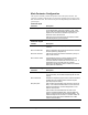
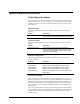
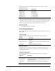
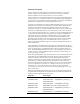
Table Of Contents
- Safety Symbol Legend
- Chapter 1 Overview
- Chapter 2 Faults and Troubleshooting
- Chapter 3 Paramters/Functions
- Introduction
- Diagnostic and Utility Functions
- Drive Configuration Functions
- General Setup Functions
- I/O Functions
- LAN Functions
- Motor Control Functions
- Protective Functions
- Custom User Faults
- DC Link Protection
- Ground Fault Protection (Fast)
- Hardware Fault Strings
- Heatsink Thermal Protection
- Line-Line Voltage Protection
- Motor Overtemperature Detection
- Phase Current Protection
- Timed Overcurrent Detection
- Transformer Overtemperature Detection
- Motor Ground Protection
- Phase Imbalance Monitor
- Line Monitor
- Phase Lock Loop
- Sequencer Functions
- Speed Reference Functions
- Speed/Torque Control Functions
- System Data Parameters
- Chapter 4 Wizards
- Introduction
- Introduction 4-1
- DAC Setup
- Drive Commissioning
- Drive Commissioning: Overview
- Drive Commissioning: Intelligent Part Number
- Drive Commissioning: Drive Units
- Drive Commissioning: AC Source Selection
- Drive Commissioning: Motor Nameplate Data
- Drive Commissioning: Motor Crossover Voltage
- Drive Commissioning: Motor Protection Class
- Drive Commissioning: Motor Poles
- Drive Commissioning: Motor Data Sheet
- Drive Commissioning: Motor Data Sheet - Equivalent Circuit Data
- Drive Commissioning: Motor Data Sheet - Flux Curve
- Drive Commissioning: Motor and Process Speed Referencing
- Drive Commissioning: Tachometer Support
- Drive Commissioning: Tachometer Pulses Per Revolution
- Drive Commissioning: Tachometer Loss Protection
- Drive Commissioning: Stopping Configuration
- Drive Commissioning: Flying Restart
- Drive Commissioning: X-Stop Configuration
- Drive Commissioning: X-Stop Ramp Time
- Drive Commissioning: Run Ready Permissive String
- Drive Commissioning: Starting and Stopping the Drive
- Drive Commissioning: Manual Reference
- Drive Commissioning: Maximum Speed References
- Drive Commissioning: Jog Speed Setpoints
- Drive Commissioning: Reference Ramp Bypass
- Drive Commissioning: Reference Ramp Mode
- Drive Commissioning: Reference Ramp Speed Independent Rates
- Drive Commissioning: Reference Ramp Speed Independent Rate Set Selection
- Drive Commissioning: Reference Ramp Programmed Acceleration Rates
- Drive Commissioning: Reference Ramp Programmed Acceleration Speeds
- Drive Commissioning: Reference Ramp Programmed Deceleration Rates
- Drive Commissioning: Reference Ramp Programmed Deceleration Speeds
- Drive Commissioning: DDI Increment and Decrement Rates (Local Mode)
- Drive Commissioning: Speed/Torque Regulator Configuration
- Drive Commissioning: Speed/Torque Regulator Modes
- Drive Commissioning: Torque Regulator Reference and Output
- Drive Commissioning: Torque with Speed Override Reference and Output
- Drive Commissioning: Torque with Speed Override Speed Error
- Drive Commissioning: Torque with Speed Override Stopping Behavior
- Drive Commissioning: Torque and Current Limits
- Drive Commissioning: Torque and Current Limits Uniform
- Drive Commissioning: Failed Calculation
- Drive Commissioning: Torque and Current Limit Selection
- Drive Commissioning: Normal Torque and Current Limits
- Drive Commissioning: Alternate Torque and Current Limits
- Drive Commissioning: Motoring Torque Limits
- Drive Commissioning: Generating Torque Limits
- Drive Commissioning: Current Limits
- Drive Commissioning: Power Dip Ride-Through
- Drive Commissioning: Parameter Calculation
- Drive Commissioning: Simulator Mode
- Drive Commissioning: Hardware Fault Strings in Simulator Mode
- Drive Commissioning: Simulator Mechanical Configuration
- Drive Commissioning: Exit Reminder
- Drive Commissioning: Conclusion
- Line Transfer Tuneup
- Motor Control Tuneup
- Panel Meter Setup
- Per Unit Setup
- Line Protection Setup
- Pulse Test
- Remaining Parameter Setup
- Simulator Setup
- Speed Regulator Tuneup
- Speed Regulator Tuneup: Model
- Speed Regulator Tuneup: System Inertia
- Speed Regulator Tuneup: Inertia Measurement Command
- Speed Regulator Tuneup: Speed Regulator Mode
- Speed Regulator Tuneup: Manual Regulator Tuneup
- Speed Regulator Tuneup: 1st Order Response
- Speed Regulator Tuneup: 2nd Order Response
- Speed Regulator Tuneup: 2nd Order Response with Stiffness Filter
- Speed Regulator Tuneup: Calculate Speed Regulator Gains Command
- Notes
- Chapter 5 Signal Mapping
- Appendix A Function Block Diagrams
- Index
- Reader Comments

3-96
•
••
•
Chapter 3 Paramters/Functions Innovation Series Medium Voltage GP Type - G Drives GEH-6385
Function description
The Speed Reference Ramp function is part of the Speed Reference Generation
function. It operates on the speed reference after the Critical Speed Avoidance
function and before its use in the Speed/Torque Overview function.
The Speed Reference Ramp function limits the rate of change of the speed reference.
Its input (Speed ref, pre ramp) may experience a step change of large magnitude. Its
output (Speed ref, ramped) has the rate limit imposed on it. The user can disable the
Speed Reference Ramp function by setting Ramp bypass to True.
The input to the Speed Reference Ramp is enabled and equal to Speed ref, pre ramp
when Ramp ref enabled is True. When Ramp ref enabled is False, the input to the
ramp is set to zero and the ramp output is allowed to decelerate to zero. More
information on Ramp ref enabled is available in the Sequencer Status function help.
If the drive is configured for flying restart (when Flying restart is set to Enable fly
restart), then the ramp output (Speed ref, ramped) is set to the speed feedback (Speed
reg fbk) when the reference input to the Speed/Torque Regulator is disabled. The
input to the Speed/Torque Regulator is disabled when Speed ref enabled is False.
This feature allows the speed reference to ramp from the speed feedback to the
specified ramp input when the Speed/Torque Regulator reference input is enabled.
More information on Flying restart is available in the Sequencer Permissives
function help. More information on Speed ref enabled is available in the Sequencer
Status function help.
Two ramp modes are available for the Speed Reference Ramp function: the speed
independent ramp rate mode and the programmed ramp rate mode. The modes differ
in the way the ramp rates are implemented. The modes are selected by Ramp rate
mode. The speed independent ramp rate mode is active when Ramp rate mode is set
to Indep accel/decel. The programmed ramp rate mode is active when Ramp rate
mode is set to Prog accel/decel.
When the speed independent ramp rate mode is active, one acceleration rate and one
deceleration rate are implemented for all speeds. The rate of change of the speed
reference is limited to the acceleration rate when the magnitude of the speed
reference is increasing. The rate of change of the speed reference is limited to the
deceleration rate when the magnitude of the speed reference is decreasing. The
acceleration and deceleration ramp rates belong to one of two ramp rate sets. Ramp
rate set 1 is defined by Acceleration rate 1 and Deceleration rate 1 and is active
when Ramp rate 2 select selects a False value. Ramp rate set 2 is defined by
Acceleration rate 2 and Deceleration rate 2 and is active when Ramp rate 2 select
selects a True value.
When the programmed ramp rate mode is active, the acceleration and deceleration
rates depend on the magnitude of the speed reference. The following table lists the
ramp rates and the regions where they are active.
Ramp rate Active region
Acceleration rate 1 Abs(Speed ref, pre ramp) <= Accel break point 1
Acceleration rate 2
Accel break point 1 < Abs(Speed ref, pre ramp) <=
Accel break point 2
Acceleration rate 3 Accel break point 2 < Abs(Speed ref, pre ramp)
Deceleration rate 1 Abs(Speed ref, pre ramp) <= Decel break point 1
Deceleration rate 2 Decel break point 1 < Abs(Speed ref, pre ramp) <=
Decel break point 2
Deceleration rate 3 Decel break point 2 < Abs(Speed ref, pre ramp)