
- General Electric Computer Accessories User Manual
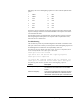
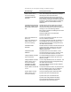
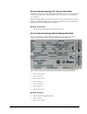
Table Of Contents
- Safety Symbol Legend
- Chapter 1 Overview
- Chapter 2 Faults and Troubleshooting
- Chapter 3 Paramters/Functions
- Introduction
- Diagnostic and Utility Functions
- Drive Configuration Functions
- General Setup Functions
- I/O Functions
- LAN Functions
- Motor Control Functions
- Protective Functions
- Custom User Faults
- DC Link Protection
- Ground Fault Protection (Fast)
- Hardware Fault Strings
- Heatsink Thermal Protection
- Line-Line Voltage Protection
- Motor Overtemperature Detection
- Phase Current Protection
- Timed Overcurrent Detection
- Transformer Overtemperature Detection
- Motor Ground Protection
- Phase Imbalance Monitor
- Line Monitor
- Phase Lock Loop
- Sequencer Functions
- Speed Reference Functions
- Speed/Torque Control Functions
- System Data Parameters
- Chapter 4 Wizards
- Introduction
- Introduction 4-1
- DAC Setup
- Drive Commissioning
- Drive Commissioning: Overview
- Drive Commissioning: Intelligent Part Number
- Drive Commissioning: Drive Units
- Drive Commissioning: AC Source Selection
- Drive Commissioning: Motor Nameplate Data
- Drive Commissioning: Motor Crossover Voltage
- Drive Commissioning: Motor Protection Class
- Drive Commissioning: Motor Poles
- Drive Commissioning: Motor Data Sheet
- Drive Commissioning: Motor Data Sheet - Equivalent Circuit Data
- Drive Commissioning: Motor Data Sheet - Flux Curve
- Drive Commissioning: Motor and Process Speed Referencing
- Drive Commissioning: Tachometer Support
- Drive Commissioning: Tachometer Pulses Per Revolution
- Drive Commissioning: Tachometer Loss Protection
- Drive Commissioning: Stopping Configuration
- Drive Commissioning: Flying Restart
- Drive Commissioning: X-Stop Configuration
- Drive Commissioning: X-Stop Ramp Time
- Drive Commissioning: Run Ready Permissive String
- Drive Commissioning: Starting and Stopping the Drive
- Drive Commissioning: Manual Reference
- Drive Commissioning: Maximum Speed References
- Drive Commissioning: Jog Speed Setpoints
- Drive Commissioning: Reference Ramp Bypass
- Drive Commissioning: Reference Ramp Mode
- Drive Commissioning: Reference Ramp Speed Independent Rates
- Drive Commissioning: Reference Ramp Speed Independent Rate Set Selection
- Drive Commissioning: Reference Ramp Programmed Acceleration Rates
- Drive Commissioning: Reference Ramp Programmed Acceleration Speeds
- Drive Commissioning: Reference Ramp Programmed Deceleration Rates
- Drive Commissioning: Reference Ramp Programmed Deceleration Speeds
- Drive Commissioning: DDI Increment and Decrement Rates (Local Mode)
- Drive Commissioning: Speed/Torque Regulator Configuration
- Drive Commissioning: Speed/Torque Regulator Modes
- Drive Commissioning: Torque Regulator Reference and Output
- Drive Commissioning: Torque with Speed Override Reference and Output
- Drive Commissioning: Torque with Speed Override Speed Error
- Drive Commissioning: Torque with Speed Override Stopping Behavior
- Drive Commissioning: Torque and Current Limits
- Drive Commissioning: Torque and Current Limits Uniform
- Drive Commissioning: Failed Calculation
- Drive Commissioning: Torque and Current Limit Selection
- Drive Commissioning: Normal Torque and Current Limits
- Drive Commissioning: Alternate Torque and Current Limits
- Drive Commissioning: Motoring Torque Limits
- Drive Commissioning: Generating Torque Limits
- Drive Commissioning: Current Limits
- Drive Commissioning: Power Dip Ride-Through
- Drive Commissioning: Parameter Calculation
- Drive Commissioning: Simulator Mode
- Drive Commissioning: Hardware Fault Strings in Simulator Mode
- Drive Commissioning: Simulator Mechanical Configuration
- Drive Commissioning: Exit Reminder
- Drive Commissioning: Conclusion
- Line Transfer Tuneup
- Motor Control Tuneup
- Panel Meter Setup
- Per Unit Setup
- Line Protection Setup
- Pulse Test
- Remaining Parameter Setup
- Simulator Setup
- Speed Regulator Tuneup
- Speed Regulator Tuneup: Model
- Speed Regulator Tuneup: System Inertia
- Speed Regulator Tuneup: Inertia Measurement Command
- Speed Regulator Tuneup: Speed Regulator Mode
- Speed Regulator Tuneup: Manual Regulator Tuneup
- Speed Regulator Tuneup: 1st Order Response
- Speed Regulator Tuneup: 2nd Order Response
- Speed Regulator Tuneup: 2nd Order Response with Stiffness Filter
- Speed Regulator Tuneup: Calculate Speed Regulator Gains Command
- Notes
- Chapter 5 Signal Mapping
- Appendix A Function Block Diagrams
- Index
- Reader Comments

GEH-6385 Reference and Troubleshooting, 2300 V Drives Chapter 4 Wizards
•
••
•
4-9
The following are descriptions of bridge test failure messages.
Error Message Description/Procedure
Short circuit detection test
failed. Check for one or
more of the following.
An undesirable conductive path was detected in the
drive. This message will be followed by messages
describing the nature of the test failure.
POSSIBLE SHORTED
DEVICES:
All IGBTs and diodes that may be shorted will be
listed. However, the short circuit detection may have
been caused by a bad gate connection or IGBTs not
switching on. This will also be listed in the following
message. Check for shorted IGBTs and clamp
diodes first.
POSSIBLE DEVICES WITH
BAD GATE CONNECTIONS
OR ARE NOT SWITCHING
ON:
All IGBTs which returned a gate drive fault during
the test will be listed. The fault could have been
caused by a shorted device as listed in the previous
message, or one of the following problems:
Bad connection between the IGDM gate drive board
and the IGBT listed
Defective IGDM board on the IGBT listed
Defective IGBT listed
Open circuit detection test
did not run.
The open circuit detection test does not run if the
short circuit detection test fails.
Open circuit detection test
failed. Check for one or
more of the following.
An expected conductive path was not detected or a
current feedback was incorrect or missing. This
message will be followed by messages describing
the nature of the test failure.
POSSIBLE OPEN
DEVICES:
All IGBTs, diodes, and load connections that may be
opened will be listed. However, the open circuit
detection may have been caused by a current
feedback (shunt) error.
POSSIBLE SHUNT
ERRORS:
All possible shunt errors will be listed. If shunt
connections appear to be correct, check for correct
current scale and offset variables in the drive.
Voltage feedback evaluation
was not performed.
The voltage feedback evaluation is not performed if
the short circuit detection test or the open circuit
detection test fails.
Voltage feedback evaluation
failed. Check for one or
more of the following.
Correct voltage feedbacks were not measured. This
message will be followed by messages describing
the nature of the test failure.
POSSIBLE VOLTAGE
FEEDBACK ERRORS:
All voltage feedbacks that did not match expected
values will be listed.
Dynamic Brake Cell Test did
not run.
The Dynamic Brake Cell Test is not performed if the
short circuit detection test, open circuit detection
test, or the voltage feedback evaluation fails.
Dynamic Brake Cell Test
failed. Check for one or
more of the following.
One of the following dynamic brake tests failed:
Dynamic brake short circuit detection test
Dynamic brake open circuit detection test
Dynamic brake voltage feedback evaluation
This message will be followed by messages
describing the nature of the test failure.