
- General Electric Computer Accessories User Manual

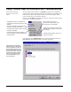


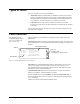
Table Of Contents
- Safety Symbol Legend
- Chapter 1 Overview
- Chapter 2 Faults and Troubleshooting
- Chapter 3 Paramters/Functions
- Introduction
- Diagnostic and Utility Functions
- Drive Configuration Functions
- General Setup Functions
- I/O Functions
- LAN Functions
- Motor Control Functions
- Protective Functions
- Custom User Faults
- DC Link Protection
- Ground Fault Protection (Fast)
- Hardware Fault Strings
- Heatsink Thermal Protection
- Line-Line Voltage Protection
- Motor Overtemperature Detection
- Phase Current Protection
- Timed Overcurrent Detection
- Transformer Overtemperature Detection
- Motor Ground Protection
- Phase Imbalance Monitor
- Line Monitor
- Phase Lock Loop
- Sequencer Functions
- Speed Reference Functions
- Speed/Torque Control Functions
- System Data Parameters
- Chapter 4 Wizards
- Introduction
- Introduction 4-1
- DAC Setup
- Drive Commissioning
- Drive Commissioning: Overview
- Drive Commissioning: Intelligent Part Number
- Drive Commissioning: Drive Units
- Drive Commissioning: AC Source Selection
- Drive Commissioning: Motor Nameplate Data
- Drive Commissioning: Motor Crossover Voltage
- Drive Commissioning: Motor Protection Class
- Drive Commissioning: Motor Poles
- Drive Commissioning: Motor Data Sheet
- Drive Commissioning: Motor Data Sheet - Equivalent Circuit Data
- Drive Commissioning: Motor Data Sheet - Flux Curve
- Drive Commissioning: Motor and Process Speed Referencing
- Drive Commissioning: Tachometer Support
- Drive Commissioning: Tachometer Pulses Per Revolution
- Drive Commissioning: Tachometer Loss Protection
- Drive Commissioning: Stopping Configuration
- Drive Commissioning: Flying Restart
- Drive Commissioning: X-Stop Configuration
- Drive Commissioning: X-Stop Ramp Time
- Drive Commissioning: Run Ready Permissive String
- Drive Commissioning: Starting and Stopping the Drive
- Drive Commissioning: Manual Reference
- Drive Commissioning: Maximum Speed References
- Drive Commissioning: Jog Speed Setpoints
- Drive Commissioning: Reference Ramp Bypass
- Drive Commissioning: Reference Ramp Mode
- Drive Commissioning: Reference Ramp Speed Independent Rates
- Drive Commissioning: Reference Ramp Speed Independent Rate Set Selection
- Drive Commissioning: Reference Ramp Programmed Acceleration Rates
- Drive Commissioning: Reference Ramp Programmed Acceleration Speeds
- Drive Commissioning: Reference Ramp Programmed Deceleration Rates
- Drive Commissioning: Reference Ramp Programmed Deceleration Speeds
- Drive Commissioning: DDI Increment and Decrement Rates (Local Mode)
- Drive Commissioning: Speed/Torque Regulator Configuration
- Drive Commissioning: Speed/Torque Regulator Modes
- Drive Commissioning: Torque Regulator Reference and Output
- Drive Commissioning: Torque with Speed Override Reference and Output
- Drive Commissioning: Torque with Speed Override Speed Error
- Drive Commissioning: Torque with Speed Override Stopping Behavior
- Drive Commissioning: Torque and Current Limits
- Drive Commissioning: Torque and Current Limits Uniform
- Drive Commissioning: Failed Calculation
- Drive Commissioning: Torque and Current Limit Selection
- Drive Commissioning: Normal Torque and Current Limits
- Drive Commissioning: Alternate Torque and Current Limits
- Drive Commissioning: Motoring Torque Limits
- Drive Commissioning: Generating Torque Limits
- Drive Commissioning: Current Limits
- Drive Commissioning: Power Dip Ride-Through
- Drive Commissioning: Parameter Calculation
- Drive Commissioning: Simulator Mode
- Drive Commissioning: Hardware Fault Strings in Simulator Mode
- Drive Commissioning: Simulator Mechanical Configuration
- Drive Commissioning: Exit Reminder
- Drive Commissioning: Conclusion
- Line Transfer Tuneup
- Motor Control Tuneup
- Panel Meter Setup
- Per Unit Setup
- Line Protection Setup
- Pulse Test
- Remaining Parameter Setup
- Simulator Setup
- Speed Regulator Tuneup
- Speed Regulator Tuneup: Model
- Speed Regulator Tuneup: System Inertia
- Speed Regulator Tuneup: Inertia Measurement Command
- Speed Regulator Tuneup: Speed Regulator Mode
- Speed Regulator Tuneup: Manual Regulator Tuneup
- Speed Regulator Tuneup: 1st Order Response
- Speed Regulator Tuneup: 2nd Order Response
- Speed Regulator Tuneup: 2nd Order Response with Stiffness Filter
- Speed Regulator Tuneup: Calculate Speed Regulator Gains Command
- Notes
- Chapter 5 Signal Mapping
- Appendix A Function Block Diagrams
- Index
- Reader Comments
2-2
•
••
•
Chapter 2 Faults and Troubleshooting Innovation Series Medium Voltage GP Type - G Drives GEH-6385
Types of Faults
There are currently two types of fault conditions:
• Alarm faults indicate conditions that you should note, but that are not serious
enough to automatically shut down or trip the drive. If the condition goes away,
some alarm faults clear themselves and the display then identifies the alarm as
brief. Otherwise, you must stop the drive to clear this type of fault.
• Trip faults indicate a more serious condition that needs to be corrected.
Therefore, it trips the drive. The drive should not be restarted until the condition
is corrected.
You can clear most faults by selecting Clear Faults on the drive’s keypad or in the
(optional) toolbox program.
Fault Indication
The DSPX board is the
IS200DSPX Digital Signal
Processor, located in the
drive control rack.
The drive indicates a fault condition on the keypad, toolbox display, and on the
DSPX board.
On the keypad, a fault icon appears in the right side of the display: The operator can
then use the keypad to access the fault/alarm description (see Figure 5-1) and to clear
the fault.
ACTIVE FAULT
50 Trip HtSink temp low,
108 Brief DC bus voltage
12 Trip Gnd flt,
113 Trip Invalid board
--- RESET FAULTS NOW --
Fault No.
Fault Behavior
Abbreviated Description
Fault Icon:
Flashing = fault
Not flashing (on steady) = alarm
Figure 2-1. Sample Fault Display Screen on Keypad
The toolbox uses a Windows-based PC display. When a fault occurs, the word
Alarm or Trip appears in the lower right corner of the screen. You can view a
description and clear the fault using the toolbox functions. (GE publication GEH-
6401 describes these tools and this feature.)
The DSPX Fault LED displays at the front of the drive’s control rack. This red
indicator is on solid for a fault and flashes for an alarm.
A fault is identified by an assigned number and abbreviated description. Both of
these are displayed when an operator examines a fault using the keypad (see Figure
2-1) or the toolbox.
Table 2-1 lists the drive faults and their probable cause.