
- General Electric Computer Accessories User Manual
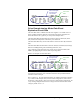
Table Of Contents
- Safety Symbol Legend
- Chapter 1 Overview
- Chapter 2 Faults and Troubleshooting
- Chapter 3 Paramters/Functions
- Introduction
- Diagnostic and Utility Functions
- Drive Configuration Functions
- General Setup Functions
- I/O Functions
- LAN Functions
- Motor Control Functions
- Protective Functions
- Custom User Faults
- DC Link Protection
- Ground Fault Protection (Fast)
- Hardware Fault Strings
- Heatsink Thermal Protection
- Line-Line Voltage Protection
- Motor Overtemperature Detection
- Phase Current Protection
- Timed Overcurrent Detection
- Transformer Overtemperature Detection
- Motor Ground Protection
- Phase Imbalance Monitor
- Line Monitor
- Phase Lock Loop
- Sequencer Functions
- Speed Reference Functions
- Speed/Torque Control Functions
- System Data Parameters
- Chapter 4 Wizards
- Introduction
- Introduction 4-1
- DAC Setup
- Drive Commissioning
- Drive Commissioning: Overview
- Drive Commissioning: Intelligent Part Number
- Drive Commissioning: Drive Units
- Drive Commissioning: AC Source Selection
- Drive Commissioning: Motor Nameplate Data
- Drive Commissioning: Motor Crossover Voltage
- Drive Commissioning: Motor Protection Class
- Drive Commissioning: Motor Poles
- Drive Commissioning: Motor Data Sheet
- Drive Commissioning: Motor Data Sheet - Equivalent Circuit Data
- Drive Commissioning: Motor Data Sheet - Flux Curve
- Drive Commissioning: Motor and Process Speed Referencing
- Drive Commissioning: Tachometer Support
- Drive Commissioning: Tachometer Pulses Per Revolution
- Drive Commissioning: Tachometer Loss Protection
- Drive Commissioning: Stopping Configuration
- Drive Commissioning: Flying Restart
- Drive Commissioning: X-Stop Configuration
- Drive Commissioning: X-Stop Ramp Time
- Drive Commissioning: Run Ready Permissive String
- Drive Commissioning: Starting and Stopping the Drive
- Drive Commissioning: Manual Reference
- Drive Commissioning: Maximum Speed References
- Drive Commissioning: Jog Speed Setpoints
- Drive Commissioning: Reference Ramp Bypass
- Drive Commissioning: Reference Ramp Mode
- Drive Commissioning: Reference Ramp Speed Independent Rates
- Drive Commissioning: Reference Ramp Speed Independent Rate Set Selection
- Drive Commissioning: Reference Ramp Programmed Acceleration Rates
- Drive Commissioning: Reference Ramp Programmed Acceleration Speeds
- Drive Commissioning: Reference Ramp Programmed Deceleration Rates
- Drive Commissioning: Reference Ramp Programmed Deceleration Speeds
- Drive Commissioning: DDI Increment and Decrement Rates (Local Mode)
- Drive Commissioning: Speed/Torque Regulator Configuration
- Drive Commissioning: Speed/Torque Regulator Modes
- Drive Commissioning: Torque Regulator Reference and Output
- Drive Commissioning: Torque with Speed Override Reference and Output
- Drive Commissioning: Torque with Speed Override Speed Error
- Drive Commissioning: Torque with Speed Override Stopping Behavior
- Drive Commissioning: Torque and Current Limits
- Drive Commissioning: Torque and Current Limits Uniform
- Drive Commissioning: Failed Calculation
- Drive Commissioning: Torque and Current Limit Selection
- Drive Commissioning: Normal Torque and Current Limits
- Drive Commissioning: Alternate Torque and Current Limits
- Drive Commissioning: Motoring Torque Limits
- Drive Commissioning: Generating Torque Limits
- Drive Commissioning: Current Limits
- Drive Commissioning: Power Dip Ride-Through
- Drive Commissioning: Parameter Calculation
- Drive Commissioning: Simulator Mode
- Drive Commissioning: Hardware Fault Strings in Simulator Mode
- Drive Commissioning: Simulator Mechanical Configuration
- Drive Commissioning: Exit Reminder
- Drive Commissioning: Conclusion
- Line Transfer Tuneup
- Motor Control Tuneup
- Panel Meter Setup
- Per Unit Setup
- Line Protection Setup
- Pulse Test
- Remaining Parameter Setup
- Simulator Setup
- Speed Regulator Tuneup
- Speed Regulator Tuneup: Model
- Speed Regulator Tuneup: System Inertia
- Speed Regulator Tuneup: Inertia Measurement Command
- Speed Regulator Tuneup: Speed Regulator Mode
- Speed Regulator Tuneup: Manual Regulator Tuneup
- Speed Regulator Tuneup: 1st Order Response
- Speed Regulator Tuneup: 2nd Order Response
- Speed Regulator Tuneup: 2nd Order Response with Stiffness Filter
- Speed Regulator Tuneup: Calculate Speed Regulator Gains Command
- Notes
- Chapter 5 Signal Mapping
- Appendix A Function Block Diagrams
- Index
- Reader Comments

4-18
•
••
•
Chapter 4 Wizards Innovation Series Medium Voltage GP Type - G Drives GEH-6385
Drive Commissioning: X-Stop Configuration
The Run req & xstop open trip fault occurs when the X stop circuit is open, the drive
is stopped, and one of the following requests is issued: Run request, Jog request, or
Full flux request.
The state of the X stop circuit is determined by the value of the variable to which
parameter X stop request sel points. The trip fault can be disabled, along with all
other X stop behavior, by setting parameter X stop request sel equal to Unused.
An X-stop can have 1 of 5 stopping behaviors as configured by the parameter X stop
mode.
Value of X stop mode Behavior
Nrml (ramp) stop The drive follows a linear speed deceleration ramp
down to zero speed as configured by the Speed
Reference Ramp function. Once the drive detects that
Speed reg fbk has reached the Zero speed level, the
sequencer disables the regulators and stops the drive.
Quick stop
The speed reference is stepped to zero so that the
speed is brought is brought to zero as quickly as
possible (the drive is in current limit). Once the drive
detects that Speed reg fbk has reached the Zero speed
level, the sequencer disables the regulators and stops
the drive.
Coast stop The regulators are immediately disabled and power is
removed from the motor so that it will coast to a stop.
The sequencer will prevent the drive from being re-
started until Speed reg fbk has reached the Zero speed
level, unless Flying restart is enabled.
Trip flt stop Behavior is similar to that of a Coast stop, except that a
Trip fault, X stop, is also generated.
Emerg ramp stop The drive follows a linear speed deceleration ramp
down to zero as configured by the parameter Emerg
ramp rate. (See also the Speed Reference Ramp.)
Once the drive detects that Speed reg fbk has reached
the Zero speed level, the sequencer disables the
regulators and stops the drive.
Once the drive is stopped, X stop active must be set False before the drive is re-
started. Otherwise, if any type of run is requested, the sequencer will generate an Run
req & xstop open Trip fault.
Drive Commissioning: X-Stop Ramp Time
X stop request sel points to the variable whose transition to False causes the drive to
stop in X-stop mode. Emerg ramp rate is used as the Ramp deceleration rate when
X-stop is active.