
- General Electric Computer Accessories User Manual
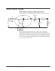
Table Of Contents
- Safety Symbol Legend
- Chapter 1 Overview
- Chapter 2 Faults and Troubleshooting
- Chapter 3 Paramters/Functions
- Introduction
- Diagnostic and Utility Functions
- Drive Configuration Functions
- General Setup Functions
- I/O Functions
- LAN Functions
- Motor Control Functions
- Protective Functions
- Custom User Faults
- DC Link Protection
- Ground Fault Protection (Fast)
- Hardware Fault Strings
- Heatsink Thermal Protection
- Line-Line Voltage Protection
- Motor Overtemperature Detection
- Phase Current Protection
- Timed Overcurrent Detection
- Transformer Overtemperature Detection
- Motor Ground Protection
- Phase Imbalance Monitor
- Line Monitor
- Phase Lock Loop
- Sequencer Functions
- Speed Reference Functions
- Speed/Torque Control Functions
- System Data Parameters
- Chapter 4 Wizards
- Introduction
- Introduction 4-1
- DAC Setup
- Drive Commissioning
- Drive Commissioning: Overview
- Drive Commissioning: Intelligent Part Number
- Drive Commissioning: Drive Units
- Drive Commissioning: AC Source Selection
- Drive Commissioning: Motor Nameplate Data
- Drive Commissioning: Motor Crossover Voltage
- Drive Commissioning: Motor Protection Class
- Drive Commissioning: Motor Poles
- Drive Commissioning: Motor Data Sheet
- Drive Commissioning: Motor Data Sheet - Equivalent Circuit Data
- Drive Commissioning: Motor Data Sheet - Flux Curve
- Drive Commissioning: Motor and Process Speed Referencing
- Drive Commissioning: Tachometer Support
- Drive Commissioning: Tachometer Pulses Per Revolution
- Drive Commissioning: Tachometer Loss Protection
- Drive Commissioning: Stopping Configuration
- Drive Commissioning: Flying Restart
- Drive Commissioning: X-Stop Configuration
- Drive Commissioning: X-Stop Ramp Time
- Drive Commissioning: Run Ready Permissive String
- Drive Commissioning: Starting and Stopping the Drive
- Drive Commissioning: Manual Reference
- Drive Commissioning: Maximum Speed References
- Drive Commissioning: Jog Speed Setpoints
- Drive Commissioning: Reference Ramp Bypass
- Drive Commissioning: Reference Ramp Mode
- Drive Commissioning: Reference Ramp Speed Independent Rates
- Drive Commissioning: Reference Ramp Speed Independent Rate Set Selection
- Drive Commissioning: Reference Ramp Programmed Acceleration Rates
- Drive Commissioning: Reference Ramp Programmed Acceleration Speeds
- Drive Commissioning: Reference Ramp Programmed Deceleration Rates
- Drive Commissioning: Reference Ramp Programmed Deceleration Speeds
- Drive Commissioning: DDI Increment and Decrement Rates (Local Mode)
- Drive Commissioning: Speed/Torque Regulator Configuration
- Drive Commissioning: Speed/Torque Regulator Modes
- Drive Commissioning: Torque Regulator Reference and Output
- Drive Commissioning: Torque with Speed Override Reference and Output
- Drive Commissioning: Torque with Speed Override Speed Error
- Drive Commissioning: Torque with Speed Override Stopping Behavior
- Drive Commissioning: Torque and Current Limits
- Drive Commissioning: Torque and Current Limits Uniform
- Drive Commissioning: Failed Calculation
- Drive Commissioning: Torque and Current Limit Selection
- Drive Commissioning: Normal Torque and Current Limits
- Drive Commissioning: Alternate Torque and Current Limits
- Drive Commissioning: Motoring Torque Limits
- Drive Commissioning: Generating Torque Limits
- Drive Commissioning: Current Limits
- Drive Commissioning: Power Dip Ride-Through
- Drive Commissioning: Parameter Calculation
- Drive Commissioning: Simulator Mode
- Drive Commissioning: Hardware Fault Strings in Simulator Mode
- Drive Commissioning: Simulator Mechanical Configuration
- Drive Commissioning: Exit Reminder
- Drive Commissioning: Conclusion
- Line Transfer Tuneup
- Motor Control Tuneup
- Panel Meter Setup
- Per Unit Setup
- Line Protection Setup
- Pulse Test
- Remaining Parameter Setup
- Simulator Setup
- Speed Regulator Tuneup
- Speed Regulator Tuneup: Model
- Speed Regulator Tuneup: System Inertia
- Speed Regulator Tuneup: Inertia Measurement Command
- Speed Regulator Tuneup: Speed Regulator Mode
- Speed Regulator Tuneup: Manual Regulator Tuneup
- Speed Regulator Tuneup: 1st Order Response
- Speed Regulator Tuneup: 2nd Order Response
- Speed Regulator Tuneup: 2nd Order Response with Stiffness Filter
- Speed Regulator Tuneup: Calculate Speed Regulator Gains Command
- Notes
- Chapter 5 Signal Mapping
- Appendix A Function Block Diagrams
- Index
- Reader Comments

GEH-6385 Reference and Troubleshooting, 2300 V Drives Chapter 4 Wizards
•
••
•
4-27
Drive Commissioning: Current Limits
Enter the normal (1) and alternate (2) per-unit current limits:
Current limit 1 will be used when Torque lim 2 sel is false.
Current limit 2 will be used when Torque lim 2 sel is true.
Drive Commissioning: Power Dip Ride-Through
Power dip ride-through can allow the drive to recover from a momentary loss of line.
The Power Dip Protection attempts to sustain DC link voltage for a selectable time
interval when a low voltage condition is detected. If the line does not recover before
the time expires, the Power dip trip fault will occur.
Related functions
• Power Dip Protection
Drive Commissioning: Parameter Calculation
A calculation is performed in the drive that sets many additional operating
parameters based on the parameters just entered. At the end of the wizard the
parameters will be uploaded to the tool with the opportunity for review.
Drive Commissioning: Simulator Mode
A Simulator mode is available in the drive. The simulator mode allows the drive to
be “run” while not necessarily attached to a motor or to a process. This can be useful
for system evaluation, troubleshooting, or training. In simulator mode the drive will
behave as if it was turning a motor providing speed, current and voltage feedbacks.
Simulated loads and inertias may be set in the menu under drive simulation
parameters.
Drive Commissioning: Hardware Fault Strings in
Simulator Mode
Two protective hardware circuits must be satisfied to allow cell firing and therefore
allow the drive to run. They are Local fault string and System fault string. These
protective strings can be ignored for the purpose of running the drive in simulator
mode. If they are not ignored, they must be satisfied to make the drive run as a
simulator.
Drive Commissioning: Simulator Mechanical
Configuration
Enter the desired values for the parameters, Simulated inertia and Sim const friction.
These parameters are the minimum required to configure the drive's mechanical
simulator. Other simulator configuration parameters are described in the Simulator
function.
Related functions
• Simulator.