
- General Electric Computer Accessories User Manual
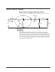
Table Of Contents
- Safety Symbol Legend
- Chapter 1 Overview
- Chapter 2 Faults and Troubleshooting
- Chapter 3 Paramters/Functions
- Introduction
- Diagnostic and Utility Functions
- Drive Configuration Functions
- General Setup Functions
- I/O Functions
- LAN Functions
- Motor Control Functions
- Protective Functions
- Custom User Faults
- DC Link Protection
- Ground Fault Protection (Fast)
- Hardware Fault Strings
- Heatsink Thermal Protection
- Line-Line Voltage Protection
- Motor Overtemperature Detection
- Phase Current Protection
- Timed Overcurrent Detection
- Transformer Overtemperature Detection
- Motor Ground Protection
- Phase Imbalance Monitor
- Line Monitor
- Phase Lock Loop
- Sequencer Functions
- Speed Reference Functions
- Speed/Torque Control Functions
- System Data Parameters
- Chapter 4 Wizards
- Introduction
- Introduction 4-1
- DAC Setup
- Drive Commissioning
- Drive Commissioning: Overview
- Drive Commissioning: Intelligent Part Number
- Drive Commissioning: Drive Units
- Drive Commissioning: AC Source Selection
- Drive Commissioning: Motor Nameplate Data
- Drive Commissioning: Motor Crossover Voltage
- Drive Commissioning: Motor Protection Class
- Drive Commissioning: Motor Poles
- Drive Commissioning: Motor Data Sheet
- Drive Commissioning: Motor Data Sheet - Equivalent Circuit Data
- Drive Commissioning: Motor Data Sheet - Flux Curve
- Drive Commissioning: Motor and Process Speed Referencing
- Drive Commissioning: Tachometer Support
- Drive Commissioning: Tachometer Pulses Per Revolution
- Drive Commissioning: Tachometer Loss Protection
- Drive Commissioning: Stopping Configuration
- Drive Commissioning: Flying Restart
- Drive Commissioning: X-Stop Configuration
- Drive Commissioning: X-Stop Ramp Time
- Drive Commissioning: Run Ready Permissive String
- Drive Commissioning: Starting and Stopping the Drive
- Drive Commissioning: Manual Reference
- Drive Commissioning: Maximum Speed References
- Drive Commissioning: Jog Speed Setpoints
- Drive Commissioning: Reference Ramp Bypass
- Drive Commissioning: Reference Ramp Mode
- Drive Commissioning: Reference Ramp Speed Independent Rates
- Drive Commissioning: Reference Ramp Speed Independent Rate Set Selection
- Drive Commissioning: Reference Ramp Programmed Acceleration Rates
- Drive Commissioning: Reference Ramp Programmed Acceleration Speeds
- Drive Commissioning: Reference Ramp Programmed Deceleration Rates
- Drive Commissioning: Reference Ramp Programmed Deceleration Speeds
- Drive Commissioning: DDI Increment and Decrement Rates (Local Mode)
- Drive Commissioning: Speed/Torque Regulator Configuration
- Drive Commissioning: Speed/Torque Regulator Modes
- Drive Commissioning: Torque Regulator Reference and Output
- Drive Commissioning: Torque with Speed Override Reference and Output
- Drive Commissioning: Torque with Speed Override Speed Error
- Drive Commissioning: Torque with Speed Override Stopping Behavior
- Drive Commissioning: Torque and Current Limits
- Drive Commissioning: Torque and Current Limits Uniform
- Drive Commissioning: Failed Calculation
- Drive Commissioning: Torque and Current Limit Selection
- Drive Commissioning: Normal Torque and Current Limits
- Drive Commissioning: Alternate Torque and Current Limits
- Drive Commissioning: Motoring Torque Limits
- Drive Commissioning: Generating Torque Limits
- Drive Commissioning: Current Limits
- Drive Commissioning: Power Dip Ride-Through
- Drive Commissioning: Parameter Calculation
- Drive Commissioning: Simulator Mode
- Drive Commissioning: Hardware Fault Strings in Simulator Mode
- Drive Commissioning: Simulator Mechanical Configuration
- Drive Commissioning: Exit Reminder
- Drive Commissioning: Conclusion
- Line Transfer Tuneup
- Motor Control Tuneup
- Panel Meter Setup
- Per Unit Setup
- Line Protection Setup
- Pulse Test
- Remaining Parameter Setup
- Simulator Setup
- Speed Regulator Tuneup
- Speed Regulator Tuneup: Model
- Speed Regulator Tuneup: System Inertia
- Speed Regulator Tuneup: Inertia Measurement Command
- Speed Regulator Tuneup: Speed Regulator Mode
- Speed Regulator Tuneup: Manual Regulator Tuneup
- Speed Regulator Tuneup: 1st Order Response
- Speed Regulator Tuneup: 2nd Order Response
- Speed Regulator Tuneup: 2nd Order Response with Stiffness Filter
- Speed Regulator Tuneup: Calculate Speed Regulator Gains Command
- Notes
- Chapter 5 Signal Mapping
- Appendix A Function Block Diagrams
- Index
- Reader Comments

GEH-6385 Reference and Troubleshooting, 2300 V Drives Chapter 4 Wizards
•
••
•
4-29
Line reference specifies the source of the utility line reference. Set to Internal to use
the internally generated line reference signal. If required by your application an
external line reference may be needed in which case set Line reference to match the
type of external line reference signal you have.
Utility swgr close specifies the I/O point that drives the utility switchgear close
command during the motor transfer sequence. Set Utility swgr close to the desired
I/O point.
MA pickup time specifies the time allowed for the MA contactor to close once it has
been commanded to close during the motor transfer sequence. Set MA pickup time to
the desired MA contactor close delay time.
For more information on the Line Transfer Tuneup wizard and issues related to the
setting of these parameters see the "Innovation Series Line Transfer Application
Guide".
Line Transfer Tuneup: Motor Capture Data
This wizard can configure the drive to perform motor transfer and capture
operations. The motor capture data parameters configure the drive to transfer a motor
to the utility line. Enter the motor capture data parameters.
Capture mtr req sel selects the signal that initiates the motor capture. Set Capture
mtr req sel to the desired signal.
Anticipated torque specifies the expected motor torque at the time of motor capture.
This parameter has an effect on the smoothness of the capture. By correctly
anticipating the amount of torque the control can more smoothly capture the motor.
This value is in PU of motor rated torque and should be determined by observing the
load torque on the motor when running at synchronous speed. If you are unsure of
the value to use then use the default value.
Utility swgr open specifies the I/O point that drives the utility switchgear open
command during the motor capture sequence. Set Utility swgr open to the desired
I/O point.
For more information on the Line Transfer Tuneup wizard see the "Innovation Series
Line Transfer Application Guide".
Line Transfer Tuneup: Operation
This wizard configures the drive to perform motor transfer and capture operations.
This is the section of the wizard that will verify operation of the MA contactor,
check for correct phase rotation at the drive output and measure the phase angle and
voltage magnitude relationships needed to carryout transfer commands in the future.
Utility characteristics can be measured while the motor is running off the utility. If
the motor is not running off the utility and cannot be started across the line,
disconnect the motor leads BEFORE running this command.
Verify that the utility switchgear permissives are correct before executing this
command so that you will be able to manually close the switchgear when asked. This
wizard will not send commands to the utility switchgear.
To proceed, click the Execute button.