
- General Electric Computer Accessories User Manual

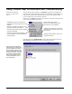


Table Of Contents
- Safety Symbol Legend
- Chapter 1 Overview
- Chapter 2 Faults and Troubleshooting
- Chapter 3 Paramters/Functions
- Introduction
- Diagnostic and Utility Functions
- Drive Configuration Functions
- General Setup Functions
- I/O Functions
- LAN Functions
- Motor Control Functions
- Protective Functions
- Custom User Faults
- DC Link Protection
- Ground Fault Protection (Fast)
- Hardware Fault Strings
- Heatsink Thermal Protection
- Line-Line Voltage Protection
- Motor Overtemperature Detection
- Phase Current Protection
- Timed Overcurrent Detection
- Transformer Overtemperature Detection
- Motor Ground Protection
- Phase Imbalance Monitor
- Line Monitor
- Phase Lock Loop
- Sequencer Functions
- Speed Reference Functions
- Speed/Torque Control Functions
- System Data Parameters
- Chapter 4 Wizards
- Introduction
- Introduction 4-1
- DAC Setup
- Drive Commissioning
- Drive Commissioning: Overview
- Drive Commissioning: Intelligent Part Number
- Drive Commissioning: Drive Units
- Drive Commissioning: AC Source Selection
- Drive Commissioning: Motor Nameplate Data
- Drive Commissioning: Motor Crossover Voltage
- Drive Commissioning: Motor Protection Class
- Drive Commissioning: Motor Poles
- Drive Commissioning: Motor Data Sheet
- Drive Commissioning: Motor Data Sheet - Equivalent Circuit Data
- Drive Commissioning: Motor Data Sheet - Flux Curve
- Drive Commissioning: Motor and Process Speed Referencing
- Drive Commissioning: Tachometer Support
- Drive Commissioning: Tachometer Pulses Per Revolution
- Drive Commissioning: Tachometer Loss Protection
- Drive Commissioning: Stopping Configuration
- Drive Commissioning: Flying Restart
- Drive Commissioning: X-Stop Configuration
- Drive Commissioning: X-Stop Ramp Time
- Drive Commissioning: Run Ready Permissive String
- Drive Commissioning: Starting and Stopping the Drive
- Drive Commissioning: Manual Reference
- Drive Commissioning: Maximum Speed References
- Drive Commissioning: Jog Speed Setpoints
- Drive Commissioning: Reference Ramp Bypass
- Drive Commissioning: Reference Ramp Mode
- Drive Commissioning: Reference Ramp Speed Independent Rates
- Drive Commissioning: Reference Ramp Speed Independent Rate Set Selection
- Drive Commissioning: Reference Ramp Programmed Acceleration Rates
- Drive Commissioning: Reference Ramp Programmed Acceleration Speeds
- Drive Commissioning: Reference Ramp Programmed Deceleration Rates
- Drive Commissioning: Reference Ramp Programmed Deceleration Speeds
- Drive Commissioning: DDI Increment and Decrement Rates (Local Mode)
- Drive Commissioning: Speed/Torque Regulator Configuration
- Drive Commissioning: Speed/Torque Regulator Modes
- Drive Commissioning: Torque Regulator Reference and Output
- Drive Commissioning: Torque with Speed Override Reference and Output
- Drive Commissioning: Torque with Speed Override Speed Error
- Drive Commissioning: Torque with Speed Override Stopping Behavior
- Drive Commissioning: Torque and Current Limits
- Drive Commissioning: Torque and Current Limits Uniform
- Drive Commissioning: Failed Calculation
- Drive Commissioning: Torque and Current Limit Selection
- Drive Commissioning: Normal Torque and Current Limits
- Drive Commissioning: Alternate Torque and Current Limits
- Drive Commissioning: Motoring Torque Limits
- Drive Commissioning: Generating Torque Limits
- Drive Commissioning: Current Limits
- Drive Commissioning: Power Dip Ride-Through
- Drive Commissioning: Parameter Calculation
- Drive Commissioning: Simulator Mode
- Drive Commissioning: Hardware Fault Strings in Simulator Mode
- Drive Commissioning: Simulator Mechanical Configuration
- Drive Commissioning: Exit Reminder
- Drive Commissioning: Conclusion
- Line Transfer Tuneup
- Motor Control Tuneup
- Panel Meter Setup
- Per Unit Setup
- Line Protection Setup
- Pulse Test
- Remaining Parameter Setup
- Simulator Setup
- Speed Regulator Tuneup
- Speed Regulator Tuneup: Model
- Speed Regulator Tuneup: System Inertia
- Speed Regulator Tuneup: Inertia Measurement Command
- Speed Regulator Tuneup: Speed Regulator Mode
- Speed Regulator Tuneup: Manual Regulator Tuneup
- Speed Regulator Tuneup: 1st Order Response
- Speed Regulator Tuneup: 2nd Order Response
- Speed Regulator Tuneup: 2nd Order Response with Stiffness Filter
- Speed Regulator Tuneup: Calculate Speed Regulator Gains Command
- Notes
- Chapter 5 Signal Mapping
- Appendix A Function Block Diagrams
- Index
- Reader Comments

2-4
•
••
•
Chapter 2 Faults and Troubleshooting Innovation Series Medium Voltage GP Type - G Drives GEH-6385
No. Name Type Description
3 Cont failed to close Trip
The Cont failed to close trip fault occurs when contactor A is commanded to
open or close and fails to do so within the allowed time (defined by parameter
MA pickup time).
Primary causes:
The contactor A feedback is missing or bad.
Possible configuration faults:
The allowed time for contactor A to open and close is too short. The allowed
time is represented by parameter MA pickup time.
Contactor A feedback is enabled when no contactor is present in the system.
In the absence of the contactor, parameter MA contactor fbk should be set
equal to Disable.
Related functions:
Main Contactor Configuration
4 Local flt Trip The Local flt trip fault occurs when the local permissive circuit is open and a
Run request, Jog request, Full flux request, or diagnostic test (cell test, pulse
test, autotune) request is issued.
Possible wiring faults:
The connections to ATBA terminal board locations 8 (L115), 10 (L24), and 12
(LCOM) are missing or damaged.
The connection to backplane connector J2 is missing or damaged.
5 Tool requested trip Trip The Tool requested trip trip fault is generated from the engineering monitor
issuing the “uf” command. It is for test purposes only.
6 Run cmd during init Alarm
The Run cmd during init alarm occurs when a Run request, Jog request, Full
flux request, or diagnostic test (cell test, pulse test, autotune) request is issued
during drive initialization. When the alarm occurs, the request to perform a
drive action is ignored.
Primary causes:
The external application layer issues a request to perform a drive action during
drive initialization.
An external input (i.e. digital input) used to request a drive action was high
during drive initialization.
7 Over speed Trip
The Over speed trip fault occurs when the magnitude of speed (variable
Speed reg fbk) is greater than the over speed threshold (parameter Over
speed flt level).
Primary causes:
Motor speed is too high.
Possible configuration faults:
Parameter Over speed flt level is set too low.
Related functions:
Speed Control Fault Check
8 Timed over current Trip The Timed over current trip fault occurs when one of the squared phase
currents (variables Ia^2 filtered, Ib^2 filtered, and Ic^2 filtered) in the timed
over current detection model exceeds the timed over current threshold level.
This fault indicates that the motor has exceeded its thermal limit.
9 EE flash corrupted Trip
The EE flash corrupted trip fault occurs when the memory containing the drive
parameters is determined to be bad during drive initialization.
EE flash corrupted requires a hard reset to clear.
Possible board failures:
DSPX