
- General Electric Computer Accessories User Manual


Table Of Contents
- Safety Symbol Legend
- Chapter 1 Overview
- Chapter 2 Faults and Troubleshooting
- Chapter 3 Paramters/Functions
- Introduction
- Diagnostic and Utility Functions
- Drive Configuration Functions
- General Setup Functions
- I/O Functions
- LAN Functions
- Motor Control Functions
- Protective Functions
- Custom User Faults
- DC Link Protection
- Ground Fault Protection (Fast)
- Hardware Fault Strings
- Heatsink Thermal Protection
- Line-Line Voltage Protection
- Motor Overtemperature Detection
- Phase Current Protection
- Timed Overcurrent Detection
- Transformer Overtemperature Detection
- Motor Ground Protection
- Phase Imbalance Monitor
- Line Monitor
- Phase Lock Loop
- Sequencer Functions
- Speed Reference Functions
- Speed/Torque Control Functions
- System Data Parameters
- Chapter 4 Wizards
- Introduction
- Introduction 4-1
- DAC Setup
- Drive Commissioning
- Drive Commissioning: Overview
- Drive Commissioning: Intelligent Part Number
- Drive Commissioning: Drive Units
- Drive Commissioning: AC Source Selection
- Drive Commissioning: Motor Nameplate Data
- Drive Commissioning: Motor Crossover Voltage
- Drive Commissioning: Motor Protection Class
- Drive Commissioning: Motor Poles
- Drive Commissioning: Motor Data Sheet
- Drive Commissioning: Motor Data Sheet - Equivalent Circuit Data
- Drive Commissioning: Motor Data Sheet - Flux Curve
- Drive Commissioning: Motor and Process Speed Referencing
- Drive Commissioning: Tachometer Support
- Drive Commissioning: Tachometer Pulses Per Revolution
- Drive Commissioning: Tachometer Loss Protection
- Drive Commissioning: Stopping Configuration
- Drive Commissioning: Flying Restart
- Drive Commissioning: X-Stop Configuration
- Drive Commissioning: X-Stop Ramp Time
- Drive Commissioning: Run Ready Permissive String
- Drive Commissioning: Starting and Stopping the Drive
- Drive Commissioning: Manual Reference
- Drive Commissioning: Maximum Speed References
- Drive Commissioning: Jog Speed Setpoints
- Drive Commissioning: Reference Ramp Bypass
- Drive Commissioning: Reference Ramp Mode
- Drive Commissioning: Reference Ramp Speed Independent Rates
- Drive Commissioning: Reference Ramp Speed Independent Rate Set Selection
- Drive Commissioning: Reference Ramp Programmed Acceleration Rates
- Drive Commissioning: Reference Ramp Programmed Acceleration Speeds
- Drive Commissioning: Reference Ramp Programmed Deceleration Rates
- Drive Commissioning: Reference Ramp Programmed Deceleration Speeds
- Drive Commissioning: DDI Increment and Decrement Rates (Local Mode)
- Drive Commissioning: Speed/Torque Regulator Configuration
- Drive Commissioning: Speed/Torque Regulator Modes
- Drive Commissioning: Torque Regulator Reference and Output
- Drive Commissioning: Torque with Speed Override Reference and Output
- Drive Commissioning: Torque with Speed Override Speed Error
- Drive Commissioning: Torque with Speed Override Stopping Behavior
- Drive Commissioning: Torque and Current Limits
- Drive Commissioning: Torque and Current Limits Uniform
- Drive Commissioning: Failed Calculation
- Drive Commissioning: Torque and Current Limit Selection
- Drive Commissioning: Normal Torque and Current Limits
- Drive Commissioning: Alternate Torque and Current Limits
- Drive Commissioning: Motoring Torque Limits
- Drive Commissioning: Generating Torque Limits
- Drive Commissioning: Current Limits
- Drive Commissioning: Power Dip Ride-Through
- Drive Commissioning: Parameter Calculation
- Drive Commissioning: Simulator Mode
- Drive Commissioning: Hardware Fault Strings in Simulator Mode
- Drive Commissioning: Simulator Mechanical Configuration
- Drive Commissioning: Exit Reminder
- Drive Commissioning: Conclusion
- Line Transfer Tuneup
- Motor Control Tuneup
- Panel Meter Setup
- Per Unit Setup
- Line Protection Setup
- Pulse Test
- Remaining Parameter Setup
- Simulator Setup
- Speed Regulator Tuneup
- Speed Regulator Tuneup: Model
- Speed Regulator Tuneup: System Inertia
- Speed Regulator Tuneup: Inertia Measurement Command
- Speed Regulator Tuneup: Speed Regulator Mode
- Speed Regulator Tuneup: Manual Regulator Tuneup
- Speed Regulator Tuneup: 1st Order Response
- Speed Regulator Tuneup: 2nd Order Response
- Speed Regulator Tuneup: 2nd Order Response with Stiffness Filter
- Speed Regulator Tuneup: Calculate Speed Regulator Gains Command
- Notes
- Chapter 5 Signal Mapping
- Appendix A Function Block Diagrams
- Index
- Reader Comments
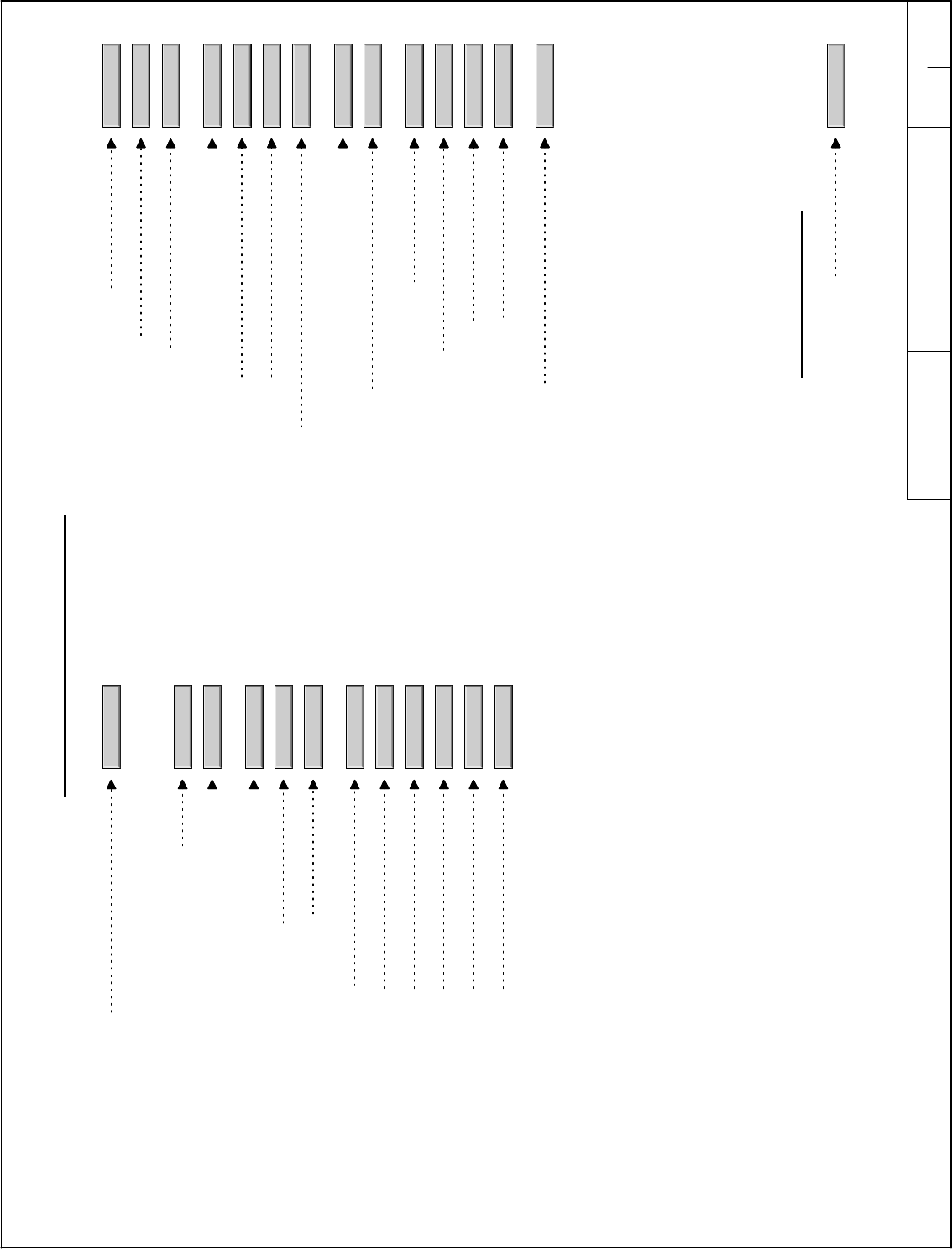
ACMVAC-G Inverter Index
Contents.vsd
Innovation Control
Device name: Date:
01
02
03
04
05
06
07
08
09
10
11
12
13
14
15
16
GE Motors and
Industrial Systems
Salem, Va. USA
PRODUCT:
01
02
03
04
05
06
07
08
09
10
11
12
13
14
15
A B C D E F G H I J K L M N O P Q R S T U
A B C D E F G H I J K L
January 14, 2000
saved date:
Page name:
Analog and Digital I/O Testing
HWIO_Tst
Factory Test Only
HWIO_Dig
3) Digital Inputs/Outputs & Mapping (HWIO)
Ovr_Seq
8) Sequencing Overview
SigMap_LAN
5) Drive LAN Signal Map
2) Contents
HWIO_Ana
4) Analog Inputs/Outputs & Mapping (HWIO)
SigMap_Bit1
6) Drive LAN Boolean Signals (bits 0-15)
SigMap_Bit2
7) Drive LAN Boolean Signals (bits 16-31)
GenSeq_1
9) General Sequencing #1
GenSeq_2
10) General Sequencing #2
GenSeq_3
11) General Sequencing #3
GenSeq_5
13) General Sequencing #5
GenSeq_4
12) General Sequencing #4
Overview
1) Hi Level Overview
Ovr_RfSel
14) Speed Reference Generation
Ramp
16) Speed Reference Ramp
CrSpdAvd
15) Critical Speed Avoidance
Diag_Util
23) Diagnostic & Utility Functions
Ovr_SpTq
17) Speed / Torque Overview
Core
21) Motor Control Interface
Spd_Fbk
18) Speed Feedback
Capture
25) Capture Buffer Configuration
SLD
24) Signal Level Detection
Ovr_MCtrl
22) Motor Control
Sreg
19) Speed Regulator
Droop
20) Droop
PosFbk
26) Position Feedback Instrument
Ovr_Lin_Mon
27) AC Line Monitor
Jun 06, 2000ISD1