
- General Electric Computer Accessories User Manual


Table Of Contents
- Safety Symbol Legend
- Chapter 1 Overview
- Chapter 2 Faults and Troubleshooting
- Chapter 3 Paramters/Functions
- Introduction
- Diagnostic and Utility Functions
- Drive Configuration Functions
- General Setup Functions
- I/O Functions
- LAN Functions
- Motor Control Functions
- Protective Functions
- Custom User Faults
- DC Link Protection
- Ground Fault Protection (Fast)
- Hardware Fault Strings
- Heatsink Thermal Protection
- Line-Line Voltage Protection
- Motor Overtemperature Detection
- Phase Current Protection
- Timed Overcurrent Detection
- Transformer Overtemperature Detection
- Motor Ground Protection
- Phase Imbalance Monitor
- Line Monitor
- Phase Lock Loop
- Sequencer Functions
- Speed Reference Functions
- Speed/Torque Control Functions
- System Data Parameters
- Chapter 4 Wizards
- Introduction
- Introduction 4-1
- DAC Setup
- Drive Commissioning
- Drive Commissioning: Overview
- Drive Commissioning: Intelligent Part Number
- Drive Commissioning: Drive Units
- Drive Commissioning: AC Source Selection
- Drive Commissioning: Motor Nameplate Data
- Drive Commissioning: Motor Crossover Voltage
- Drive Commissioning: Motor Protection Class
- Drive Commissioning: Motor Poles
- Drive Commissioning: Motor Data Sheet
- Drive Commissioning: Motor Data Sheet - Equivalent Circuit Data
- Drive Commissioning: Motor Data Sheet - Flux Curve
- Drive Commissioning: Motor and Process Speed Referencing
- Drive Commissioning: Tachometer Support
- Drive Commissioning: Tachometer Pulses Per Revolution
- Drive Commissioning: Tachometer Loss Protection
- Drive Commissioning: Stopping Configuration
- Drive Commissioning: Flying Restart
- Drive Commissioning: X-Stop Configuration
- Drive Commissioning: X-Stop Ramp Time
- Drive Commissioning: Run Ready Permissive String
- Drive Commissioning: Starting and Stopping the Drive
- Drive Commissioning: Manual Reference
- Drive Commissioning: Maximum Speed References
- Drive Commissioning: Jog Speed Setpoints
- Drive Commissioning: Reference Ramp Bypass
- Drive Commissioning: Reference Ramp Mode
- Drive Commissioning: Reference Ramp Speed Independent Rates
- Drive Commissioning: Reference Ramp Speed Independent Rate Set Selection
- Drive Commissioning: Reference Ramp Programmed Acceleration Rates
- Drive Commissioning: Reference Ramp Programmed Acceleration Speeds
- Drive Commissioning: Reference Ramp Programmed Deceleration Rates
- Drive Commissioning: Reference Ramp Programmed Deceleration Speeds
- Drive Commissioning: DDI Increment and Decrement Rates (Local Mode)
- Drive Commissioning: Speed/Torque Regulator Configuration
- Drive Commissioning: Speed/Torque Regulator Modes
- Drive Commissioning: Torque Regulator Reference and Output
- Drive Commissioning: Torque with Speed Override Reference and Output
- Drive Commissioning: Torque with Speed Override Speed Error
- Drive Commissioning: Torque with Speed Override Stopping Behavior
- Drive Commissioning: Torque and Current Limits
- Drive Commissioning: Torque and Current Limits Uniform
- Drive Commissioning: Failed Calculation
- Drive Commissioning: Torque and Current Limit Selection
- Drive Commissioning: Normal Torque and Current Limits
- Drive Commissioning: Alternate Torque and Current Limits
- Drive Commissioning: Motoring Torque Limits
- Drive Commissioning: Generating Torque Limits
- Drive Commissioning: Current Limits
- Drive Commissioning: Power Dip Ride-Through
- Drive Commissioning: Parameter Calculation
- Drive Commissioning: Simulator Mode
- Drive Commissioning: Hardware Fault Strings in Simulator Mode
- Drive Commissioning: Simulator Mechanical Configuration
- Drive Commissioning: Exit Reminder
- Drive Commissioning: Conclusion
- Line Transfer Tuneup
- Motor Control Tuneup
- Panel Meter Setup
- Per Unit Setup
- Line Protection Setup
- Pulse Test
- Remaining Parameter Setup
- Simulator Setup
- Speed Regulator Tuneup
- Speed Regulator Tuneup: Model
- Speed Regulator Tuneup: System Inertia
- Speed Regulator Tuneup: Inertia Measurement Command
- Speed Regulator Tuneup: Speed Regulator Mode
- Speed Regulator Tuneup: Manual Regulator Tuneup
- Speed Regulator Tuneup: 1st Order Response
- Speed Regulator Tuneup: 2nd Order Response
- Speed Regulator Tuneup: 2nd Order Response with Stiffness Filter
- Speed Regulator Tuneup: Calculate Speed Regulator Gains Command
- Notes
- Chapter 5 Signal Mapping
- Appendix A Function Block Diagrams
- Index
- Reader Comments
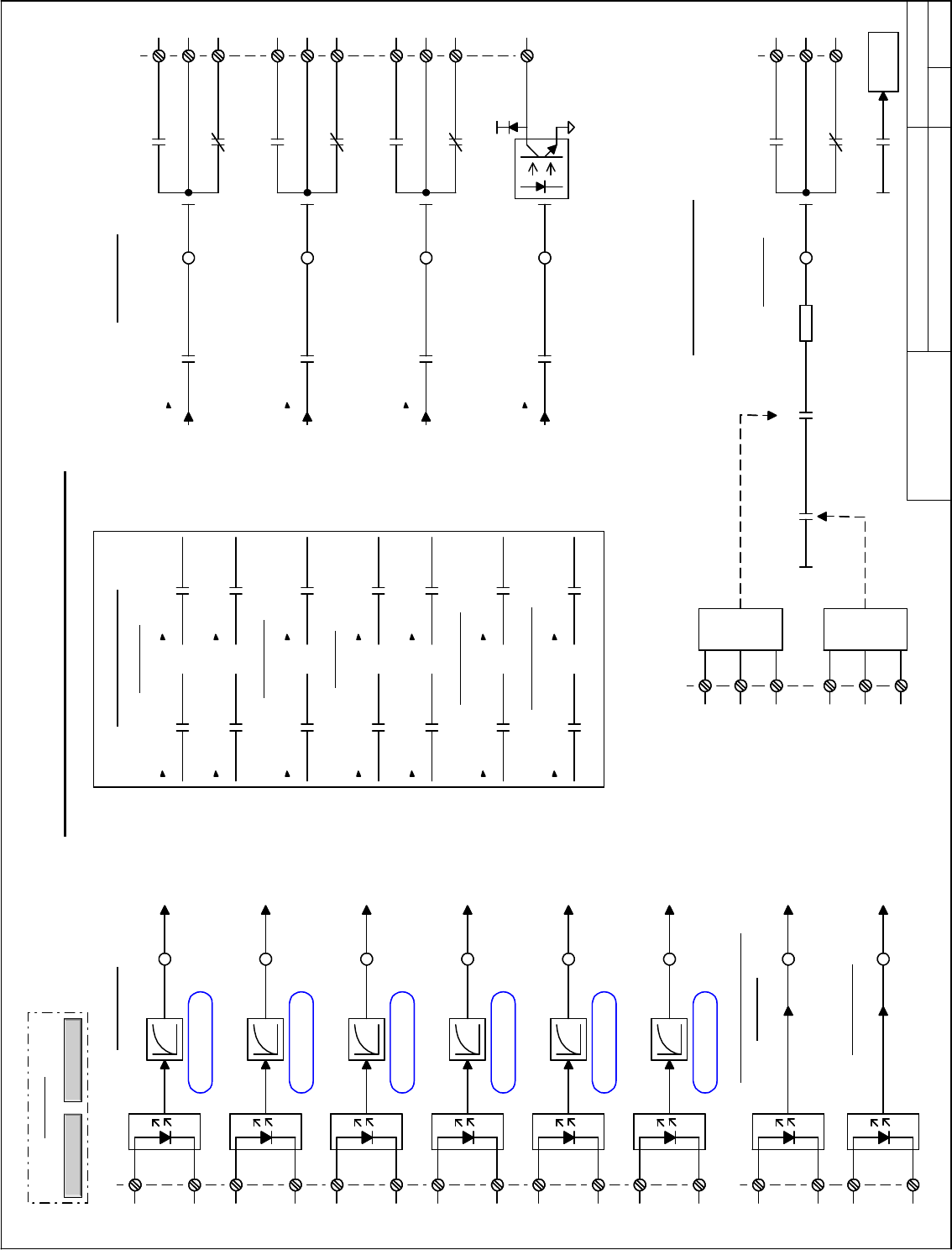
Digital Inputs/Outputs & Mapping
Overview
Overview
NAVIGATION
HWIO_Dig.vsd
Innovation Control
Device name: Date:
01
02
03
04
05
06
07
08
09
10
11
12
13
14
15
16
GE Motors and
Industrial Systems
Salem, Va. USA
PRODUCT:
01
02
03
04
05
06
07
08
09
10
11
12
13
14
15
A B C D E F G H I J K L M N O P Q R S T U
A B C D E F G H I J K L
March 10, 1999
saved date:
Page name:
Sequencing Selectors
Digital Inputs
HWIO_Ana
Analog I/O
Tachometer Marker
MA Feedback
*
- 2-5ms HW Filtering
*
1-
16
1+
14
*
2-
20
2+
18
*
3-
24
3+
22
*
4-
28
4+
26
*
5-
32
5+
30
*
6-
36
6+
34
*
MA-
9
MA+
7
/MKR
53
MKR
51
Dedicated Digital Inputs
Relay Outputs
+24Vdc
R1NO
15
R1NC
19
R2NO
21
R2NC
25
R3NO
27
R3NC
31
DRVR
11
MANO
1
MANC
5
S24V
4
L24V
10
S115V
2
L115V
8
SCOM
6
LCOM
12
MACOM
3
R1COM
17
R2COM
23
R3COM
29
ATBA
ATBA
MA Pilot Relay
Dedicated Relay Outputs
ATBA
Stop Commands
Faults & Reset
Permissives
Run / Jog Requests
Regulator Commands
ATBA
ATBA
Logic
P5
S
Y
S
T
E
M
F
A
U
L
T
L
O
C
A
L
F
A
U
L
T
24COM
I
To Bridge
Enable
NotNot
Jun 06, 2000ISD1
Fault reset select
Unused boolean
Run permissive sel
Unused boolean
Run request select
Unused boolean
Jog request select
Unused boolean
Full flux req sel
Unused boolean
MA close req sel
Unused boolean
Reverse select
Unused boolean
X stop request sel
Unused boolean
Digital input 1
VCO 3 unfiltered
Digital in 1 filter
0
Digital input 2
Digital in 2 filter
0
Digital input 3
Digital in 3 filter
0
Digital input 4
Digital in 4 filter
0
Digital input 5
Digital in 5 filter
0
Digital input 6
Digital in 6 filter
0
Start permissive sel
Unused boolean
MA contactor closed
Relay 1 state
Relay 2 state
Relay 3 state
Solid state relay
Relay 1 state
Relay 1 state
Relay 2 state
Relay 2 state
Relay 3 state
Relay 3 state
MA close command
MA close command
MA close command
Relay 1 select
Unused boolean
Relay 2 select
Unused boolean
Relay 3 select
Unused boolean
SS relay driver sel
Unused boolean
Stop PB select
Unused boolean
User NC fault sel
Unused boolean
User NO fault sel
Unused boolean
Motor OT fault sel
Unused boolean
Torque mode sel
Force True
MA close command
System fault stringLocal fault string