
- General Electric Computer Accessories User Manual


Table Of Contents
- Safety Symbol Legend
- Chapter 1 Overview
- Chapter 2 Faults and Troubleshooting
- Chapter 3 Paramters/Functions
- Introduction
- Diagnostic and Utility Functions
- Drive Configuration Functions
- General Setup Functions
- I/O Functions
- LAN Functions
- Motor Control Functions
- Protective Functions
- Custom User Faults
- DC Link Protection
- Ground Fault Protection (Fast)
- Hardware Fault Strings
- Heatsink Thermal Protection
- Line-Line Voltage Protection
- Motor Overtemperature Detection
- Phase Current Protection
- Timed Overcurrent Detection
- Transformer Overtemperature Detection
- Motor Ground Protection
- Phase Imbalance Monitor
- Line Monitor
- Phase Lock Loop
- Sequencer Functions
- Speed Reference Functions
- Speed/Torque Control Functions
- System Data Parameters
- Chapter 4 Wizards
- Introduction
- Introduction 4-1
- DAC Setup
- Drive Commissioning
- Drive Commissioning: Overview
- Drive Commissioning: Intelligent Part Number
- Drive Commissioning: Drive Units
- Drive Commissioning: AC Source Selection
- Drive Commissioning: Motor Nameplate Data
- Drive Commissioning: Motor Crossover Voltage
- Drive Commissioning: Motor Protection Class
- Drive Commissioning: Motor Poles
- Drive Commissioning: Motor Data Sheet
- Drive Commissioning: Motor Data Sheet - Equivalent Circuit Data
- Drive Commissioning: Motor Data Sheet - Flux Curve
- Drive Commissioning: Motor and Process Speed Referencing
- Drive Commissioning: Tachometer Support
- Drive Commissioning: Tachometer Pulses Per Revolution
- Drive Commissioning: Tachometer Loss Protection
- Drive Commissioning: Stopping Configuration
- Drive Commissioning: Flying Restart
- Drive Commissioning: X-Stop Configuration
- Drive Commissioning: X-Stop Ramp Time
- Drive Commissioning: Run Ready Permissive String
- Drive Commissioning: Starting and Stopping the Drive
- Drive Commissioning: Manual Reference
- Drive Commissioning: Maximum Speed References
- Drive Commissioning: Jog Speed Setpoints
- Drive Commissioning: Reference Ramp Bypass
- Drive Commissioning: Reference Ramp Mode
- Drive Commissioning: Reference Ramp Speed Independent Rates
- Drive Commissioning: Reference Ramp Speed Independent Rate Set Selection
- Drive Commissioning: Reference Ramp Programmed Acceleration Rates
- Drive Commissioning: Reference Ramp Programmed Acceleration Speeds
- Drive Commissioning: Reference Ramp Programmed Deceleration Rates
- Drive Commissioning: Reference Ramp Programmed Deceleration Speeds
- Drive Commissioning: DDI Increment and Decrement Rates (Local Mode)
- Drive Commissioning: Speed/Torque Regulator Configuration
- Drive Commissioning: Speed/Torque Regulator Modes
- Drive Commissioning: Torque Regulator Reference and Output
- Drive Commissioning: Torque with Speed Override Reference and Output
- Drive Commissioning: Torque with Speed Override Speed Error
- Drive Commissioning: Torque with Speed Override Stopping Behavior
- Drive Commissioning: Torque and Current Limits
- Drive Commissioning: Torque and Current Limits Uniform
- Drive Commissioning: Failed Calculation
- Drive Commissioning: Torque and Current Limit Selection
- Drive Commissioning: Normal Torque and Current Limits
- Drive Commissioning: Alternate Torque and Current Limits
- Drive Commissioning: Motoring Torque Limits
- Drive Commissioning: Generating Torque Limits
- Drive Commissioning: Current Limits
- Drive Commissioning: Power Dip Ride-Through
- Drive Commissioning: Parameter Calculation
- Drive Commissioning: Simulator Mode
- Drive Commissioning: Hardware Fault Strings in Simulator Mode
- Drive Commissioning: Simulator Mechanical Configuration
- Drive Commissioning: Exit Reminder
- Drive Commissioning: Conclusion
- Line Transfer Tuneup
- Motor Control Tuneup
- Panel Meter Setup
- Per Unit Setup
- Line Protection Setup
- Pulse Test
- Remaining Parameter Setup
- Simulator Setup
- Speed Regulator Tuneup
- Speed Regulator Tuneup: Model
- Speed Regulator Tuneup: System Inertia
- Speed Regulator Tuneup: Inertia Measurement Command
- Speed Regulator Tuneup: Speed Regulator Mode
- Speed Regulator Tuneup: Manual Regulator Tuneup
- Speed Regulator Tuneup: 1st Order Response
- Speed Regulator Tuneup: 2nd Order Response
- Speed Regulator Tuneup: 2nd Order Response with Stiffness Filter
- Speed Regulator Tuneup: Calculate Speed Regulator Gains Command
- Notes
- Chapter 5 Signal Mapping
- Appendix A Function Block Diagrams
- Index
- Reader Comments
SigMap_LAN.vsd
Innovation Control
Device name: Date:
01
02
03
04
05
06
07
08
09
10
11
12
13
14
15
16
GE Motors and
Industrial Systems
Salem, Va. USA
PRODUCT:
01
02
03
04
05
06
07
08
09
10
11
12
13
14
15
A B C D E F G H I J K L M N O P Q R S T U
A B C D E F G H I J K L
June 4, 1998
saved date:
Page name:
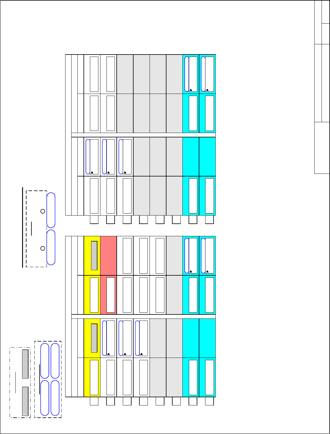
Drive Lan Signal Map
SigMap_Bit1 Overview
NextBack
NAVIGATION
Request bits 1, lan
Reference
(see table)
Variable Functionality
1
2
3
4
5
6
7
8
Feedbck bits 1, lan
Feedback
Signal Functionality
active fault number:
1) highest severity,
2) earliest time-stamp
Page 1
Reference
Variable Functionality
1
2
3
4
5
6
7
8
Feedback
Signal Functionality
Page 2
SigMap_Bit1
(see table)
SigMap_Bit1
averaged
averaged
general purpose
real var
general purpose
real var
general purpose
real var
<spare>
<spare>
<spare><spare>
Status
<spare>
<spare>
Configuration
general purpose
real var
<spare>
<spare>
averaged
<spare>
<spare>
averaged
averaged
Jun 06, 2000ISD1
Auto speed ref, lan
Spd ref offset, lan
Torque ref, lan
GP lan ref 1
GP lan ref 2
Auto analog ref sel
Constant float 0.0
Torque ref select
Constant float 0.0
Fault number
Speed feedback, lan
Motor torque, lan
Motor current, lan
GP lan fbk reg 1
GP lan fbk reg 2
GP lan fbk reg 1 sel
Unused float
GP lan fbk reg 2 sel
Unused float
Flux reference, lan
Droop comp ref, lan
GP lan ref 3
GP lan ref 4
Flux ref ratio sel
Unused float
GP lan fbk reg 3
GP lan fbk reg 4
GP lan fbk reg 3 sel
Unused float
GP lan fbk reg 4 sel
Unused float
Torque fdfwd, lan Motor power, lan
Motor voltage, lan
Speed loop sum sel
Constant float 0.0
Droop comp ref sel
Constant float 0.0
Torque feed fwd sel
Constant float 0.0
LAN connection ok LAN commands OK
Network interface
None
LAN fbk avg time
0 Sec
LAN cmds inhibit
No
LAN trips inhibit
No
Sys ISBus node #
-1
LAN frame time
1 ms Sec
Speed feedback
Torque fbk, calced
Motor current
Motor power
Motor voltage
SigMap_LAN.vsd
Innovation Control
Device name: Date:
01
02
03
04
05
06
07
08
09
10
11
12
13
14
15
16
GE Motors and
Industrial Systems
Salem, Va. USA
PRODUCT:
01
02
03
04
05
06
07
08
09
10
11
12
13
14
15
A B C D E F G H I J K L M N O P Q R S T U
A B C D E F G H I J K L
June 4, 1998
saved date:
Page name:
Drive Lan Signal Map
SigMap_Bit1 Overview
NextBack
NAVIGATION
Request bits 1, lan
Reference
(see table)
Variable Functionality
1
2
3
4
5
6
7
8
Feedbck bits 1, lan
Feedback
Signal Functionality
active fault number:
1) highest severity,
2) earliest time-stamp
Page 1
Reference
Variable Functionality
1
2
3
4
5
6
7
8
Feedback
Signal Functionality
Page 2
SigMap_Bit1
(see table)
SigMap_Bit1
averaged
averaged
general purpose
real var
general purpose
real var
general purpose
real var
<spare>
<spare>
<spare><spare>
Status
<spare>
<spare>
Configuration
general purpose
real var
<spare>
<spare>
averaged
<spare>
<spare>
averaged
averaged
Jun 06, 2000ISD1
Auto speed ref, lan
Spd ref offset, lan
Torque ref, lan
GP lan ref 1
GP lan ref 2
Auto analog ref sel
Constant float 0.0
Torque ref select
Constant float 0.0
Fault number
Speed feedback, lan
Motor torque, lan
Motor current, lan
GP lan fbk reg 1
GP lan fbk reg 2
GP lan fbk reg 1 sel
Unused float
GP lan fbk reg 2 sel
Unused float
Flux reference, lan
Droop comp ref, lan
GP lan ref 3
GP lan ref 4
Flux ref ratio sel
Unused float
GP lan fbk reg 3
GP lan fbk reg 4
GP lan fbk reg 3 sel
Unused float
GP lan fbk reg 4 sel
Unused float
Torque fdfwd, lan Motor power, lan
Motor voltage, lan
Speed loop sum sel
Constant float 0.0
Droop comp ref sel
Constant float 0.0
Torque feed fwd sel
Constant float 0.0
LAN connection ok LAN commands OK
Network interface
None
LAN fbk avg time
0 Sec
LAN cmds inhibit
No
LAN trips inhibit
No
Sys ISBus node #
-1
LAN frame time
1 ms Sec
Speed feedback
Torque fbk, calced
Motor current
Motor power
Motor voltage