
- General Electric Computer Accessories User Manual


Table Of Contents
- Safety Symbol Legend
- Chapter 1 Overview
- Chapter 2 Faults and Troubleshooting
- Chapter 3 Paramters/Functions
- Introduction
- Diagnostic and Utility Functions
- Drive Configuration Functions
- General Setup Functions
- I/O Functions
- LAN Functions
- Motor Control Functions
- Protective Functions
- Custom User Faults
- DC Link Protection
- Ground Fault Protection (Fast)
- Hardware Fault Strings
- Heatsink Thermal Protection
- Line-Line Voltage Protection
- Motor Overtemperature Detection
- Phase Current Protection
- Timed Overcurrent Detection
- Transformer Overtemperature Detection
- Motor Ground Protection
- Phase Imbalance Monitor
- Line Monitor
- Phase Lock Loop
- Sequencer Functions
- Speed Reference Functions
- Speed/Torque Control Functions
- System Data Parameters
- Chapter 4 Wizards
- Introduction
- Introduction 4-1
- DAC Setup
- Drive Commissioning
- Drive Commissioning: Overview
- Drive Commissioning: Intelligent Part Number
- Drive Commissioning: Drive Units
- Drive Commissioning: AC Source Selection
- Drive Commissioning: Motor Nameplate Data
- Drive Commissioning: Motor Crossover Voltage
- Drive Commissioning: Motor Protection Class
- Drive Commissioning: Motor Poles
- Drive Commissioning: Motor Data Sheet
- Drive Commissioning: Motor Data Sheet - Equivalent Circuit Data
- Drive Commissioning: Motor Data Sheet - Flux Curve
- Drive Commissioning: Motor and Process Speed Referencing
- Drive Commissioning: Tachometer Support
- Drive Commissioning: Tachometer Pulses Per Revolution
- Drive Commissioning: Tachometer Loss Protection
- Drive Commissioning: Stopping Configuration
- Drive Commissioning: Flying Restart
- Drive Commissioning: X-Stop Configuration
- Drive Commissioning: X-Stop Ramp Time
- Drive Commissioning: Run Ready Permissive String
- Drive Commissioning: Starting and Stopping the Drive
- Drive Commissioning: Manual Reference
- Drive Commissioning: Maximum Speed References
- Drive Commissioning: Jog Speed Setpoints
- Drive Commissioning: Reference Ramp Bypass
- Drive Commissioning: Reference Ramp Mode
- Drive Commissioning: Reference Ramp Speed Independent Rates
- Drive Commissioning: Reference Ramp Speed Independent Rate Set Selection
- Drive Commissioning: Reference Ramp Programmed Acceleration Rates
- Drive Commissioning: Reference Ramp Programmed Acceleration Speeds
- Drive Commissioning: Reference Ramp Programmed Deceleration Rates
- Drive Commissioning: Reference Ramp Programmed Deceleration Speeds
- Drive Commissioning: DDI Increment and Decrement Rates (Local Mode)
- Drive Commissioning: Speed/Torque Regulator Configuration
- Drive Commissioning: Speed/Torque Regulator Modes
- Drive Commissioning: Torque Regulator Reference and Output
- Drive Commissioning: Torque with Speed Override Reference and Output
- Drive Commissioning: Torque with Speed Override Speed Error
- Drive Commissioning: Torque with Speed Override Stopping Behavior
- Drive Commissioning: Torque and Current Limits
- Drive Commissioning: Torque and Current Limits Uniform
- Drive Commissioning: Failed Calculation
- Drive Commissioning: Torque and Current Limit Selection
- Drive Commissioning: Normal Torque and Current Limits
- Drive Commissioning: Alternate Torque and Current Limits
- Drive Commissioning: Motoring Torque Limits
- Drive Commissioning: Generating Torque Limits
- Drive Commissioning: Current Limits
- Drive Commissioning: Power Dip Ride-Through
- Drive Commissioning: Parameter Calculation
- Drive Commissioning: Simulator Mode
- Drive Commissioning: Hardware Fault Strings in Simulator Mode
- Drive Commissioning: Simulator Mechanical Configuration
- Drive Commissioning: Exit Reminder
- Drive Commissioning: Conclusion
- Line Transfer Tuneup
- Motor Control Tuneup
- Panel Meter Setup
- Per Unit Setup
- Line Protection Setup
- Pulse Test
- Remaining Parameter Setup
- Simulator Setup
- Speed Regulator Tuneup
- Speed Regulator Tuneup: Model
- Speed Regulator Tuneup: System Inertia
- Speed Regulator Tuneup: Inertia Measurement Command
- Speed Regulator Tuneup: Speed Regulator Mode
- Speed Regulator Tuneup: Manual Regulator Tuneup
- Speed Regulator Tuneup: 1st Order Response
- Speed Regulator Tuneup: 2nd Order Response
- Speed Regulator Tuneup: 2nd Order Response with Stiffness Filter
- Speed Regulator Tuneup: Calculate Speed Regulator Gains Command
- Notes
- Chapter 5 Signal Mapping
- Appendix A Function Block Diagrams
- Index
- Reader Comments
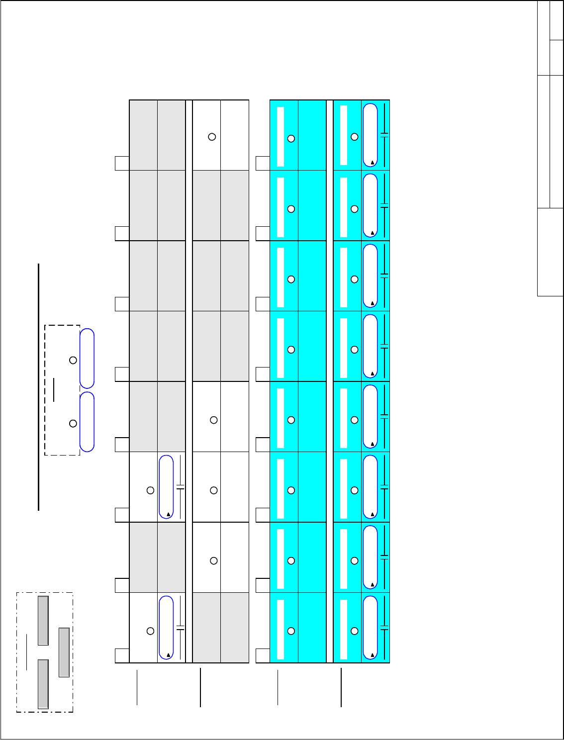
Drive Lan Boolean Signals (bits 16-31)
SigMap_Bit2.vsd
Innovation Control
Device name: Date:
01
02
03
04
05
06
07
08
09
10
11
12
13
14
15
16
GE Motors and
Industrial Systems
Salem, Va. USA
PRODUCT:
01
02
03
04
05
06
07
08
09
10
11
12
13
14
15
A B C D E F G H I J K L M N O P Q R S T U
A B C D E F G H I J K L
June 10, 1999
saved date:
Page name:
Status
16 17 18 19 20 21 22 23
Variable
Function
Signal
Function
Request Bits
Feedback Bits
24 25 26 27 28 29 30 31
Variable
Function
Signal
Function
Request Bits
Feedback Bits
general purpose
boolean var
general purpose
boolean var
general purpose
boolean var
general purpose
boolean var
general purpose
boolean var
general purpose
boolean var
general purpose
boolean var
general purpose
boolean var
speed feedback is
below zero speed
(after delay)
seq task status;
real or modeled
contactor status
SigMap_LAN SigMap_Bit1
Back toBack
NAVIGATION
Overview
Back to
result of Auto mode
requests
diagnostic
boolean var
Jun 06, 2000ISD1
LAN connection ok LAN commands OK
GP lan req bit 1
GP lan fbk bit 1 sel
Unused boolean
GP lan fbk bit 1
GP lan req bit 2
GP lan fbk bit 2 sel
Unused boolean
GP lan fbk bit 2
GP lan req bit 3
GP lan fbk bit 3 sel
Unused boolean
GP lan fbk bit 3
GP lan req bit 4
GP lan fbk bit 4 sel
Unused boolean
GP lan fbk bit 4
GP lan req bit 5
GP lan fbk bit 5 sel
Unused boolean
GP lan fbk bit 5
GP lan req bit 6
GP lan fbk bit 6 sel
Unused boolean
GP lan fbk bit 6
GP lan req bit 7
GP lan fbk bit 7 sel
Unused boolean
GP lan fbk bit 7
GP lan req bit 8
GP lan fbk bit 8 sel
Unused boolean
GP lan fbk bit 8
Ramp rate 2 sel, lan Auto mode req, lan
Ramp rate 2 select
Force False
Auto mode select
Force False
MA cont enable stat Zero speed active
LAN cmds inhibit
No
LAN trips inhibit
No
Auto mode active
Lan diag fbk bit 1