
- General Electric Computer Accessories User Manual


Table Of Contents
- Safety Symbol Legend
- Chapter 1 Overview
- Chapter 2 Faults and Troubleshooting
- Chapter 3 Paramters/Functions
- Introduction
- Diagnostic and Utility Functions
- Drive Configuration Functions
- General Setup Functions
- I/O Functions
- LAN Functions
- Motor Control Functions
- Protective Functions
- Custom User Faults
- DC Link Protection
- Ground Fault Protection (Fast)
- Hardware Fault Strings
- Heatsink Thermal Protection
- Line-Line Voltage Protection
- Motor Overtemperature Detection
- Phase Current Protection
- Timed Overcurrent Detection
- Transformer Overtemperature Detection
- Motor Ground Protection
- Phase Imbalance Monitor
- Line Monitor
- Phase Lock Loop
- Sequencer Functions
- Speed Reference Functions
- Speed/Torque Control Functions
- System Data Parameters
- Chapter 4 Wizards
- Introduction
- Introduction 4-1
- DAC Setup
- Drive Commissioning
- Drive Commissioning: Overview
- Drive Commissioning: Intelligent Part Number
- Drive Commissioning: Drive Units
- Drive Commissioning: AC Source Selection
- Drive Commissioning: Motor Nameplate Data
- Drive Commissioning: Motor Crossover Voltage
- Drive Commissioning: Motor Protection Class
- Drive Commissioning: Motor Poles
- Drive Commissioning: Motor Data Sheet
- Drive Commissioning: Motor Data Sheet - Equivalent Circuit Data
- Drive Commissioning: Motor Data Sheet - Flux Curve
- Drive Commissioning: Motor and Process Speed Referencing
- Drive Commissioning: Tachometer Support
- Drive Commissioning: Tachometer Pulses Per Revolution
- Drive Commissioning: Tachometer Loss Protection
- Drive Commissioning: Stopping Configuration
- Drive Commissioning: Flying Restart
- Drive Commissioning: X-Stop Configuration
- Drive Commissioning: X-Stop Ramp Time
- Drive Commissioning: Run Ready Permissive String
- Drive Commissioning: Starting and Stopping the Drive
- Drive Commissioning: Manual Reference
- Drive Commissioning: Maximum Speed References
- Drive Commissioning: Jog Speed Setpoints
- Drive Commissioning: Reference Ramp Bypass
- Drive Commissioning: Reference Ramp Mode
- Drive Commissioning: Reference Ramp Speed Independent Rates
- Drive Commissioning: Reference Ramp Speed Independent Rate Set Selection
- Drive Commissioning: Reference Ramp Programmed Acceleration Rates
- Drive Commissioning: Reference Ramp Programmed Acceleration Speeds
- Drive Commissioning: Reference Ramp Programmed Deceleration Rates
- Drive Commissioning: Reference Ramp Programmed Deceleration Speeds
- Drive Commissioning: DDI Increment and Decrement Rates (Local Mode)
- Drive Commissioning: Speed/Torque Regulator Configuration
- Drive Commissioning: Speed/Torque Regulator Modes
- Drive Commissioning: Torque Regulator Reference and Output
- Drive Commissioning: Torque with Speed Override Reference and Output
- Drive Commissioning: Torque with Speed Override Speed Error
- Drive Commissioning: Torque with Speed Override Stopping Behavior
- Drive Commissioning: Torque and Current Limits
- Drive Commissioning: Torque and Current Limits Uniform
- Drive Commissioning: Failed Calculation
- Drive Commissioning: Torque and Current Limit Selection
- Drive Commissioning: Normal Torque and Current Limits
- Drive Commissioning: Alternate Torque and Current Limits
- Drive Commissioning: Motoring Torque Limits
- Drive Commissioning: Generating Torque Limits
- Drive Commissioning: Current Limits
- Drive Commissioning: Power Dip Ride-Through
- Drive Commissioning: Parameter Calculation
- Drive Commissioning: Simulator Mode
- Drive Commissioning: Hardware Fault Strings in Simulator Mode
- Drive Commissioning: Simulator Mechanical Configuration
- Drive Commissioning: Exit Reminder
- Drive Commissioning: Conclusion
- Line Transfer Tuneup
- Motor Control Tuneup
- Panel Meter Setup
- Per Unit Setup
- Line Protection Setup
- Pulse Test
- Remaining Parameter Setup
- Simulator Setup
- Speed Regulator Tuneup
- Speed Regulator Tuneup: Model
- Speed Regulator Tuneup: System Inertia
- Speed Regulator Tuneup: Inertia Measurement Command
- Speed Regulator Tuneup: Speed Regulator Mode
- Speed Regulator Tuneup: Manual Regulator Tuneup
- Speed Regulator Tuneup: 1st Order Response
- Speed Regulator Tuneup: 2nd Order Response
- Speed Regulator Tuneup: 2nd Order Response with Stiffness Filter
- Speed Regulator Tuneup: Calculate Speed Regulator Gains Command
- Notes
- Chapter 5 Signal Mapping
- Appendix A Function Block Diagrams
- Index
- Reader Comments
Ovr_Lin_Mon.vsd
Innovation Series
Device name: Date:
01
02
03
04
05
06
07
08
09
10
11
12
13
14
15
16
GE Motors and
Industrial Systems
Salem, Va. USA
PRODUCT:
01
02
03
04
05
06
07
08
09
10
11
12
13
14
15
A B C D E F G H I J K L M N O P Q R S T U
A B C D E F G H I J K L
November 18, 1998
Version --- Issued
Date:
Page name:
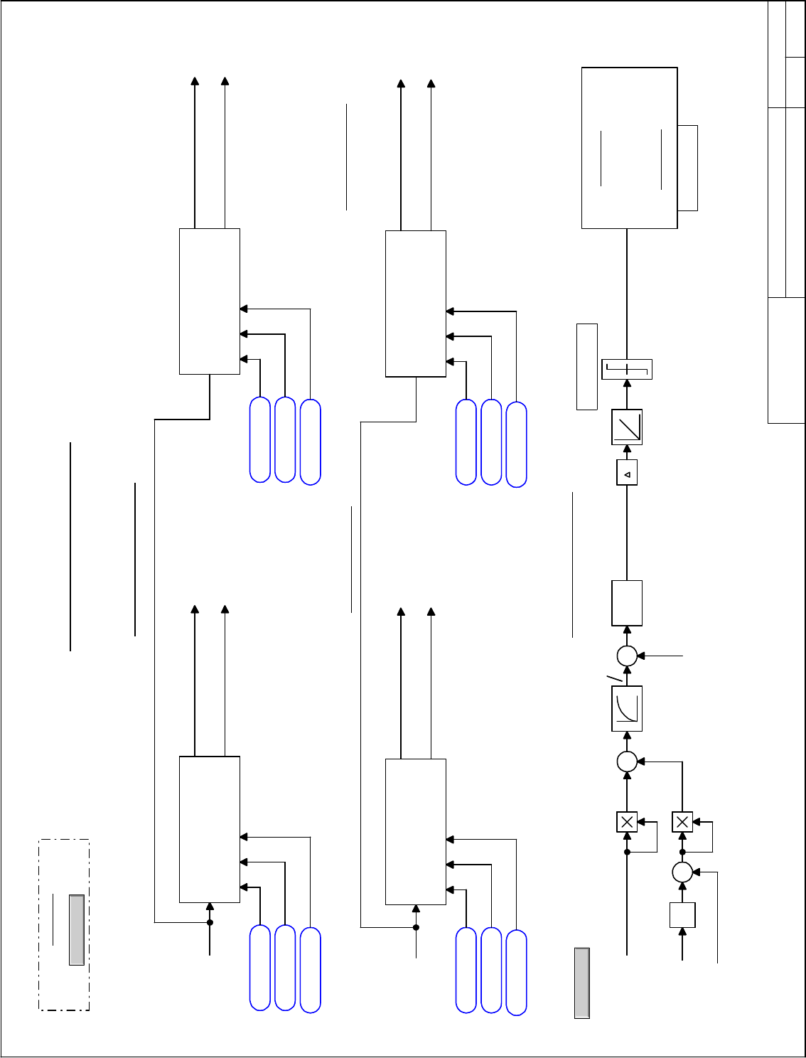
Line Monitor Overview
Overview
Back to Overview
NAVIGATION
Ovr_Pll
abs
Σ
+
-
Σ
+
+
Σ
+
-
T1-->T2
Averager
t
0.0
Alarm = Ac_Line_Tran when
V.Ph_Imb_Int in upper clamp.
Increment timer when
V.Ph_Imb_Int in upper clamp.
If timer reaches V.Ph_Imb_Tm,
Fault = Ac_Line_Wdog.
Over-voltage
Alarm and Fault
Detection
Flt. AC line voltage high
Flt. AC line over voltage
Under-voltage
Alarm and Fault
Detection
Flt. AC line volts low
Flt. AC line under volt
Voltage Magnitude Monitor
Phase Imbalance Monitor
Over-frequency
Alarm and Fault
Detection
Under-frequency
Alarm and Fault
Detection
Frequency Monitor
Flt. AC line freq high
Flt. AC line over freq
Flt. AC line freq low
Flt. AC line under freq
Frequency Monitor
Jun 06, 2000ISD1
PLL error
X axis line voltage
AC line magnitude
Phase imbalance ref
Phase imbalance avg
Phs imbalance limit
Phase imbalance int
Phs imbalance time
Line monitor volt
Line OV fault level
<No Value> V rms
Line OV alarm level
<No Value> V rms
Line OV alarm clear
<No Value> V rms
Line UV fault level
<No Value> V rms
Line UV alarm level
<No Value> V rms
Line UV alarm clear
<No Value> V rms
Line monitor volt
Line monitor frq
Over freq flt level
<No Value> Hz
Over freq alm level
<No Value> Hz
Over freq alm clear
<No Value> Hz
Under freq flt level
<No Value> Hz
Under freq alm level
<No Value> Hz
Under freq alarm clr
<No Value> Hz
Line monitor frq
Phase imbalance sqr
Ovr_Lin_Mon.vsd
Innovation Series
Device name: Date:
01
02
03
04
05
06
07
08
09
10
11
12
13
14
15
16
GE Motors and
Industrial Systems
Salem, Va. USA
PRODUCT:
01
02
03
04
05
06
07
08
09
10
11
12
13
14
15
A B C D E F G H I J K L M N O P Q R S T U
A B C D E F G H I J K L
November 18, 1998
Version --- Issued
Date:
Page name:
Line Monitor Overview
Overview
Back to Overview
NAVIGATION
Ovr_Pll
abs
Σ
+
-
Σ
+
+
Σ
+
-
T1-->T2
Averager
t
0.0
Alarm = Ac_Line_Tran when
V.Ph_Imb_Int in upper clamp.
Increment timer when
V.Ph_Imb_Int in upper clamp.
If timer reaches V.Ph_Imb_Tm,
Fault = Ac_Line_Wdog.
Over-voltage
Alarm and Fault
Detection
Flt. AC line voltage high
Flt. AC line over voltage
Under-voltage
Alarm and Fault
Detection
Flt. AC line volts low
Flt. AC line under volt
Voltage Magnitude Monitor
Phase Imbalance Monitor
Over-frequency
Alarm and Fault
Detection
Under-frequency
Alarm and Fault
Detection
Frequency Monitor
Flt. AC line freq high
Flt. AC line over freq
Flt. AC line freq low
Flt. AC line under freq
Frequency Monitor
Jun 06, 2000ISD1
PLL error
X axis line voltage
AC line magnitude
Phase imbalance ref
Phase imbalance avg
Phs imbalance limit
Phase imbalance int
Phs imbalance time
Line monitor volt
Line OV fault level
<No Value> V rms
Line OV alarm level
<No Value> V rms
Line OV alarm clear
<No Value> V rms
Line UV fault level
<No Value> V rms
Line UV alarm level
<No Value> V rms
Line UV alarm clear
<No Value> V rms
Line monitor volt
Line monitor frq
Over freq flt level
<No Value> Hz
Over freq alm level
<No Value> Hz
Over freq alm clear
<No Value> Hz
Under freq flt level
<No Value> Hz
Under freq alm level
<No Value> Hz
Under freq alarm clr
<No Value> Hz
Line monitor frq
Phase imbalance sqr