
- General Electric Computer Accessories User Manual


Table Of Contents
- Safety Symbol Legend
- Chapter 1 Overview
- Chapter 2 Faults and Troubleshooting
- Chapter 3 Paramters/Functions
- Introduction
- Diagnostic and Utility Functions
- Drive Configuration Functions
- General Setup Functions
- I/O Functions
- LAN Functions
- Motor Control Functions
- Protective Functions
- Custom User Faults
- DC Link Protection
- Ground Fault Protection (Fast)
- Hardware Fault Strings
- Heatsink Thermal Protection
- Line-Line Voltage Protection
- Motor Overtemperature Detection
- Phase Current Protection
- Timed Overcurrent Detection
- Transformer Overtemperature Detection
- Motor Ground Protection
- Phase Imbalance Monitor
- Line Monitor
- Phase Lock Loop
- Sequencer Functions
- Speed Reference Functions
- Speed/Torque Control Functions
- System Data Parameters
- Chapter 4 Wizards
- Introduction
- Introduction 4-1
- DAC Setup
- Drive Commissioning
- Drive Commissioning: Overview
- Drive Commissioning: Intelligent Part Number
- Drive Commissioning: Drive Units
- Drive Commissioning: AC Source Selection
- Drive Commissioning: Motor Nameplate Data
- Drive Commissioning: Motor Crossover Voltage
- Drive Commissioning: Motor Protection Class
- Drive Commissioning: Motor Poles
- Drive Commissioning: Motor Data Sheet
- Drive Commissioning: Motor Data Sheet - Equivalent Circuit Data
- Drive Commissioning: Motor Data Sheet - Flux Curve
- Drive Commissioning: Motor and Process Speed Referencing
- Drive Commissioning: Tachometer Support
- Drive Commissioning: Tachometer Pulses Per Revolution
- Drive Commissioning: Tachometer Loss Protection
- Drive Commissioning: Stopping Configuration
- Drive Commissioning: Flying Restart
- Drive Commissioning: X-Stop Configuration
- Drive Commissioning: X-Stop Ramp Time
- Drive Commissioning: Run Ready Permissive String
- Drive Commissioning: Starting and Stopping the Drive
- Drive Commissioning: Manual Reference
- Drive Commissioning: Maximum Speed References
- Drive Commissioning: Jog Speed Setpoints
- Drive Commissioning: Reference Ramp Bypass
- Drive Commissioning: Reference Ramp Mode
- Drive Commissioning: Reference Ramp Speed Independent Rates
- Drive Commissioning: Reference Ramp Speed Independent Rate Set Selection
- Drive Commissioning: Reference Ramp Programmed Acceleration Rates
- Drive Commissioning: Reference Ramp Programmed Acceleration Speeds
- Drive Commissioning: Reference Ramp Programmed Deceleration Rates
- Drive Commissioning: Reference Ramp Programmed Deceleration Speeds
- Drive Commissioning: DDI Increment and Decrement Rates (Local Mode)
- Drive Commissioning: Speed/Torque Regulator Configuration
- Drive Commissioning: Speed/Torque Regulator Modes
- Drive Commissioning: Torque Regulator Reference and Output
- Drive Commissioning: Torque with Speed Override Reference and Output
- Drive Commissioning: Torque with Speed Override Speed Error
- Drive Commissioning: Torque with Speed Override Stopping Behavior
- Drive Commissioning: Torque and Current Limits
- Drive Commissioning: Torque and Current Limits Uniform
- Drive Commissioning: Failed Calculation
- Drive Commissioning: Torque and Current Limit Selection
- Drive Commissioning: Normal Torque and Current Limits
- Drive Commissioning: Alternate Torque and Current Limits
- Drive Commissioning: Motoring Torque Limits
- Drive Commissioning: Generating Torque Limits
- Drive Commissioning: Current Limits
- Drive Commissioning: Power Dip Ride-Through
- Drive Commissioning: Parameter Calculation
- Drive Commissioning: Simulator Mode
- Drive Commissioning: Hardware Fault Strings in Simulator Mode
- Drive Commissioning: Simulator Mechanical Configuration
- Drive Commissioning: Exit Reminder
- Drive Commissioning: Conclusion
- Line Transfer Tuneup
- Motor Control Tuneup
- Panel Meter Setup
- Per Unit Setup
- Line Protection Setup
- Pulse Test
- Remaining Parameter Setup
- Simulator Setup
- Speed Regulator Tuneup
- Speed Regulator Tuneup: Model
- Speed Regulator Tuneup: System Inertia
- Speed Regulator Tuneup: Inertia Measurement Command
- Speed Regulator Tuneup: Speed Regulator Mode
- Speed Regulator Tuneup: Manual Regulator Tuneup
- Speed Regulator Tuneup: 1st Order Response
- Speed Regulator Tuneup: 2nd Order Response
- Speed Regulator Tuneup: 2nd Order Response with Stiffness Filter
- Speed Regulator Tuneup: Calculate Speed Regulator Gains Command
- Notes
- Chapter 5 Signal Mapping
- Appendix A Function Block Diagrams
- Index
- Reader Comments
Ovr_RfSel.vsd
Innovation Control
Device name: Date:
01
02
03
04
05
06
07
08
09
10
11
12
13
14
15
16
GE Motors and
Industrial Systems
Salem, Va. USA
PRODUCT:
01
02
03
04
05
06
07
08
09
10
11
12
13
14
15
A B C D E F G H I J K L M N O P Q R S T U
A B C D E F G H I J K L
March 10, 1998
saved date:
Page name:
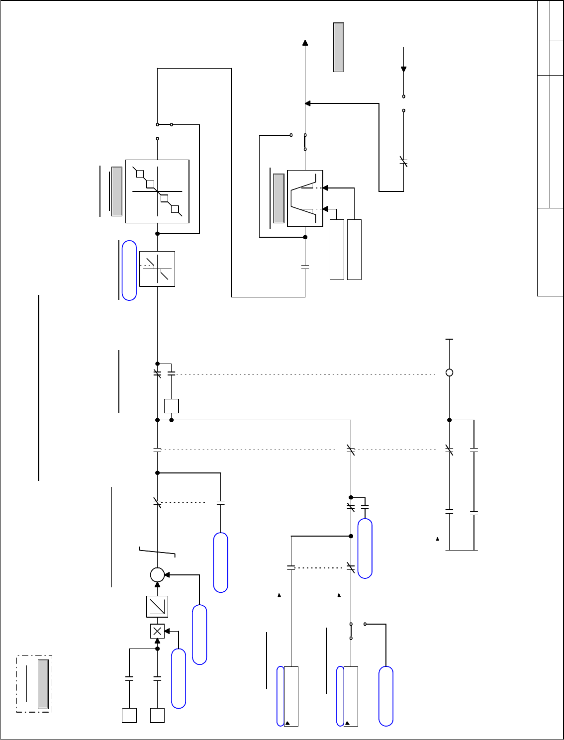
Speed Reference Generation
Drive Diagnostic Reference
-1
1
-1
Forward/Reverse
0
Reference Ramp
F
Ramp
Overview
Back to Overview
NAVIGATION
Ovr_SpTq
To Speed Regulator
Min Speed Limit
F
Critical Speed
Avoidance
CrSpdAvd
Σ
+
+
Auto Reference
Manual Reference
T
T
Speed ref, pre ramp
Speed ref, ramped
Jun 06, 2000ISD1
Applied top RPM
<No Value> RPM
Ramp ref enabled
Local mode active
Local mode active
Local Inc/Dec rate
50 RPM/s
Local speed
0 RPM
Local inc command
Local dec command
Local jog speed
60 RPM
Reverse mode active
Ramp bypass
Jog request
Jog request
Local rev request
Reverse select
Unused boolean
Local mode active
Local mode active Reverse mode active
Jog request
Man analog ref sel
Constant float 0.0
Minimum speed
0 RPM
Speed setpoint 0
0 RPM
Manual speed ref sel
Ramp accel rate
Ramp decel rate
Remote jog speed
60 RPM
Auto mode select
Force False
Auto analog ref sel
Constant float 0.0
Auto mode select
Force False
Crit speed avoidance
Speed reference
Flying restartSpeed ref enabled
Speed reg fbk
Ovr_RfSel.vsd
Innovation Control
Device name: Date:
01
02
03
04
05
06
07
08
09
10
11
12
13
14
15
16
GE Motors and
Industrial Systems
Salem, Va. USA
PRODUCT:
01
02
03
04
05
06
07
08
09
10
11
12
13
14
15
A B C D E F G H I J K L M N O P Q R S T U
A B C D E F G H I J K L
March 10, 1998
saved date:
Page name:
Speed Reference Generation
Drive Diagnostic Reference
-1
1
-1
Forward/Reverse
0
Reference Ramp
F
Ramp
Overview
Back to Overview
NAVIGATION
Ovr_SpTq
To Speed Regulator
Min Speed Limit
F
Critical Speed
Avoidance
CrSpdAvd
Σ
+
+
Auto Reference
Manual Reference
T
T
Speed ref, pre ramp
Speed ref, ramped
Jun 06, 2000ISD1
Applied top RPM
<No Value> RPM
Ramp ref enabled
Local mode active
Local mode active
Local Inc/Dec rate
50 RPM/s
Local speed
0 RPM
Local inc command
Local dec command
Local jog speed
60 RPM
Reverse mode active
Ramp bypass
Jog request
Jog request
Local rev request
Reverse select
Unused boolean
Local mode active
Local mode active Reverse mode active
Jog request
Man analog ref sel
Constant float 0.0
Minimum speed
0 RPM
Speed setpoint 0
0 RPM
Manual speed ref sel
Ramp accel rate
Ramp decel rate
Remote jog speed
60 RPM
Auto mode select
Force False
Auto analog ref sel
Constant float 0.0
Auto mode select
Force False
Crit speed avoidance
Speed reference
Flying restartSpeed ref enabled
Speed reg fbk