
- General Electric Computer Accessories User Manual


Table Of Contents
- Safety Symbol Legend
- Chapter 1 Overview
- Chapter 2 Faults and Troubleshooting
- Chapter 3 Paramters/Functions
- Introduction
- Diagnostic and Utility Functions
- Drive Configuration Functions
- General Setup Functions
- I/O Functions
- LAN Functions
- Motor Control Functions
- Protective Functions
- Custom User Faults
- DC Link Protection
- Ground Fault Protection (Fast)
- Hardware Fault Strings
- Heatsink Thermal Protection
- Line-Line Voltage Protection
- Motor Overtemperature Detection
- Phase Current Protection
- Timed Overcurrent Detection
- Transformer Overtemperature Detection
- Motor Ground Protection
- Phase Imbalance Monitor
- Line Monitor
- Phase Lock Loop
- Sequencer Functions
- Speed Reference Functions
- Speed/Torque Control Functions
- System Data Parameters
- Chapter 4 Wizards
- Introduction
- Introduction 4-1
- DAC Setup
- Drive Commissioning
- Drive Commissioning: Overview
- Drive Commissioning: Intelligent Part Number
- Drive Commissioning: Drive Units
- Drive Commissioning: AC Source Selection
- Drive Commissioning: Motor Nameplate Data
- Drive Commissioning: Motor Crossover Voltage
- Drive Commissioning: Motor Protection Class
- Drive Commissioning: Motor Poles
- Drive Commissioning: Motor Data Sheet
- Drive Commissioning: Motor Data Sheet - Equivalent Circuit Data
- Drive Commissioning: Motor Data Sheet - Flux Curve
- Drive Commissioning: Motor and Process Speed Referencing
- Drive Commissioning: Tachometer Support
- Drive Commissioning: Tachometer Pulses Per Revolution
- Drive Commissioning: Tachometer Loss Protection
- Drive Commissioning: Stopping Configuration
- Drive Commissioning: Flying Restart
- Drive Commissioning: X-Stop Configuration
- Drive Commissioning: X-Stop Ramp Time
- Drive Commissioning: Run Ready Permissive String
- Drive Commissioning: Starting and Stopping the Drive
- Drive Commissioning: Manual Reference
- Drive Commissioning: Maximum Speed References
- Drive Commissioning: Jog Speed Setpoints
- Drive Commissioning: Reference Ramp Bypass
- Drive Commissioning: Reference Ramp Mode
- Drive Commissioning: Reference Ramp Speed Independent Rates
- Drive Commissioning: Reference Ramp Speed Independent Rate Set Selection
- Drive Commissioning: Reference Ramp Programmed Acceleration Rates
- Drive Commissioning: Reference Ramp Programmed Acceleration Speeds
- Drive Commissioning: Reference Ramp Programmed Deceleration Rates
- Drive Commissioning: Reference Ramp Programmed Deceleration Speeds
- Drive Commissioning: DDI Increment and Decrement Rates (Local Mode)
- Drive Commissioning: Speed/Torque Regulator Configuration
- Drive Commissioning: Speed/Torque Regulator Modes
- Drive Commissioning: Torque Regulator Reference and Output
- Drive Commissioning: Torque with Speed Override Reference and Output
- Drive Commissioning: Torque with Speed Override Speed Error
- Drive Commissioning: Torque with Speed Override Stopping Behavior
- Drive Commissioning: Torque and Current Limits
- Drive Commissioning: Torque and Current Limits Uniform
- Drive Commissioning: Failed Calculation
- Drive Commissioning: Torque and Current Limit Selection
- Drive Commissioning: Normal Torque and Current Limits
- Drive Commissioning: Alternate Torque and Current Limits
- Drive Commissioning: Motoring Torque Limits
- Drive Commissioning: Generating Torque Limits
- Drive Commissioning: Current Limits
- Drive Commissioning: Power Dip Ride-Through
- Drive Commissioning: Parameter Calculation
- Drive Commissioning: Simulator Mode
- Drive Commissioning: Hardware Fault Strings in Simulator Mode
- Drive Commissioning: Simulator Mechanical Configuration
- Drive Commissioning: Exit Reminder
- Drive Commissioning: Conclusion
- Line Transfer Tuneup
- Motor Control Tuneup
- Panel Meter Setup
- Per Unit Setup
- Line Protection Setup
- Pulse Test
- Remaining Parameter Setup
- Simulator Setup
- Speed Regulator Tuneup
- Speed Regulator Tuneup: Model
- Speed Regulator Tuneup: System Inertia
- Speed Regulator Tuneup: Inertia Measurement Command
- Speed Regulator Tuneup: Speed Regulator Mode
- Speed Regulator Tuneup: Manual Regulator Tuneup
- Speed Regulator Tuneup: 1st Order Response
- Speed Regulator Tuneup: 2nd Order Response
- Speed Regulator Tuneup: 2nd Order Response with Stiffness Filter
- Speed Regulator Tuneup: Calculate Speed Regulator Gains Command
- Notes
- Chapter 5 Signal Mapping
- Appendix A Function Block Diagrams
- Index
- Reader Comments
January 29, 1999
Core.vsd
Innovation Control
Device name: Date:
01
02
03
04
05
06
07
08
09
10
11
12
13
14
15
16
GE Motors and
Industrial Systems
Salem, Va. USA
PRODUCT:
01
02
03
04
05
06
07
08
09
10
11
12
13
14
15
A B C D E F G H I J K L M N O P Q R S T U
A B C D E F G H I J K L
saved date:
Page name:
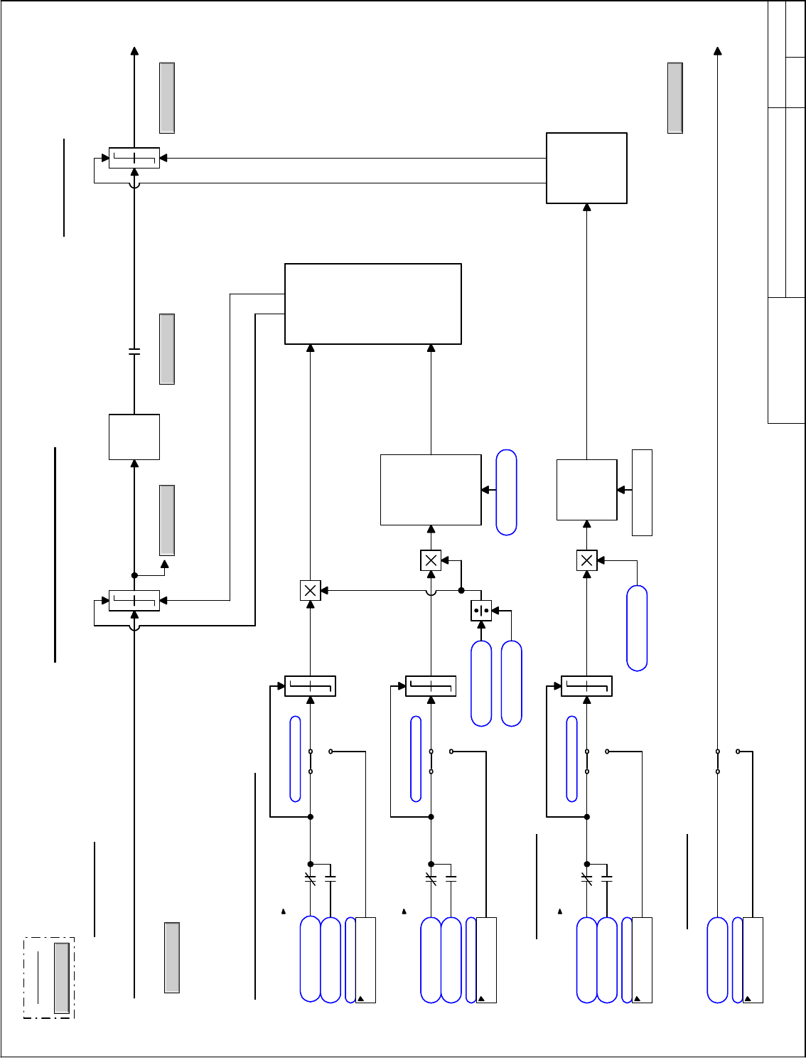
Motor Control Interface
From Speed Regulator
Ovr_SpTq
Back to Overview
NAVIGATION
SReg
Torque Command
Motoring & Generating Torque Limit Select
Torque
Compen-
sation
Current Command
Current Limit Select
Motoring &
Generating Limit
Steering Control
Ovr_MCtrl
To Motor Control
Current
Magnitude
Limit
Pullout Limit
Adjustment
and
Power-Dip
Clamp
Control
DC Bus
Regen Control
can reduce
Generating
Limit
Not Used
Not Used
Not Used
From Sequencer
GenSeq_5
To Droop Feedback
Droop
0
0
0
Flux Adjust Select
Not Used
Ovr_MCtrl
To Motor Control
Jun 06, 2000ISD1
Current limit
Torque ref pre limit
Torque current limit
Torque lim 2 sel
Force False
Torque lim 2 sel
Force False
Torque lim 2 sel
Force False
Motoring torque lim
Regen torque limit
Torque ref post lim
Motoring torque lim1
1 pu
Motoring torque lim2
1 pu
Regen torque lim 1
1 pu
Regen torque lim 2
1 pu
Trq cur ref pre lim
Current limit 1
1 pu
Current limit 2
1 pu
Torque current ref
Motor rated current
<No Value> Amps
Adj mtr trq lim sel
Unused float
Adj gen trq lim sel
Unused float
100% Motor torque
Adj cur lim ref sel
Unused float
Motor rated power
<No Value> KW
Motor rated rpm
<No Value> RPM
Flux current, avg
Adj mtr trq lim sel
Adj gen trq lim sel
Adj cur lim ref sel
Dc source
Rectifier without DB
Torque enable req
Ix command pos limit
Torque cmd neg limit
Ix command neg limit
Torque cmd pos limit
Flux ref ratio setpt
1
Flux ref ratio sel
Unused float
Flux ref ratio sel
Flux ref ratio
January 29, 1999
Core.vsd
Innovation Control
Device name: Date:
01
02
03
04
05
06
07
08
09
10
11
12
13
14
15
16
GE Motors and
Industrial Systems
Salem, Va. USA
PRODUCT:
01
02
03
04
05
06
07
08
09
10
11
12
13
14
15
A B C D E F G H I J K L M N O P Q R S T U
A B C D E F G H I J K L
saved date:
Page name:
Motor Control Interface
From Speed Regulator
Ovr_SpTq
Back to Overview
NAVIGATION
SReg
Torque Command
Motoring & Generating Torque Limit Select
Torque
Compen-
sation
Current Command
Current Limit Select
Motoring &
Generating Limit
Steering Control
Ovr_MCtrl
To Motor Control
Current
Magnitude
Limit
Pullout Limit
Adjustment
and
Power-Dip
Clamp
Control
DC Bus
Regen Control
can reduce
Generating
Limit
Not Used
Not Used
Not Used
From Sequencer
GenSeq_5
To Droop Feedback
Droop
0
0
0
Flux Adjust Select
Not Used
Ovr_MCtrl
To Motor Control
Jun 06, 2000ISD1
Current limit
Torque ref pre limit
Torque current limit
Torque lim 2 sel
Force False
Torque lim 2 sel
Force False
Torque lim 2 sel
Force False
Motoring torque lim
Regen torque limit
Torque ref post lim
Motoring torque lim1
1 pu
Motoring torque lim2
1 pu
Regen torque lim 1
1 pu
Regen torque lim 2
1 pu
Trq cur ref pre lim
Current limit 1
1 pu
Current limit 2
1 pu
Torque current ref
Motor rated current
<No Value> Amps
Adj mtr trq lim sel
Unused float
Adj gen trq lim sel
Unused float
100% Motor torque
Adj cur lim ref sel
Unused float
Motor rated power
<No Value> KW
Motor rated rpm
<No Value> RPM
Flux current, avg
Adj mtr trq lim sel
Adj gen trq lim sel
Adj cur lim ref sel
Dc source
Rectifier without DB
Torque enable req
Ix command pos limit
Torque cmd neg limit
Ix command neg limit
Torque cmd pos limit
Flux ref ratio setpt
1
Flux ref ratio sel
Unused float
Flux ref ratio sel
Flux ref ratio