
- General Electric Computer Accessories User Manual


Table Of Contents
- Safety Symbol Legend
- Chapter 1 Overview
- Chapter 2 Faults and Troubleshooting
- Chapter 3 Paramters/Functions
- Introduction
- Diagnostic and Utility Functions
- Drive Configuration Functions
- General Setup Functions
- I/O Functions
- LAN Functions
- Motor Control Functions
- Protective Functions
- Custom User Faults
- DC Link Protection
- Ground Fault Protection (Fast)
- Hardware Fault Strings
- Heatsink Thermal Protection
- Line-Line Voltage Protection
- Motor Overtemperature Detection
- Phase Current Protection
- Timed Overcurrent Detection
- Transformer Overtemperature Detection
- Motor Ground Protection
- Phase Imbalance Monitor
- Line Monitor
- Phase Lock Loop
- Sequencer Functions
- Speed Reference Functions
- Speed/Torque Control Functions
- System Data Parameters
- Chapter 4 Wizards
- Introduction
- Introduction 4-1
- DAC Setup
- Drive Commissioning
- Drive Commissioning: Overview
- Drive Commissioning: Intelligent Part Number
- Drive Commissioning: Drive Units
- Drive Commissioning: AC Source Selection
- Drive Commissioning: Motor Nameplate Data
- Drive Commissioning: Motor Crossover Voltage
- Drive Commissioning: Motor Protection Class
- Drive Commissioning: Motor Poles
- Drive Commissioning: Motor Data Sheet
- Drive Commissioning: Motor Data Sheet - Equivalent Circuit Data
- Drive Commissioning: Motor Data Sheet - Flux Curve
- Drive Commissioning: Motor and Process Speed Referencing
- Drive Commissioning: Tachometer Support
- Drive Commissioning: Tachometer Pulses Per Revolution
- Drive Commissioning: Tachometer Loss Protection
- Drive Commissioning: Stopping Configuration
- Drive Commissioning: Flying Restart
- Drive Commissioning: X-Stop Configuration
- Drive Commissioning: X-Stop Ramp Time
- Drive Commissioning: Run Ready Permissive String
- Drive Commissioning: Starting and Stopping the Drive
- Drive Commissioning: Manual Reference
- Drive Commissioning: Maximum Speed References
- Drive Commissioning: Jog Speed Setpoints
- Drive Commissioning: Reference Ramp Bypass
- Drive Commissioning: Reference Ramp Mode
- Drive Commissioning: Reference Ramp Speed Independent Rates
- Drive Commissioning: Reference Ramp Speed Independent Rate Set Selection
- Drive Commissioning: Reference Ramp Programmed Acceleration Rates
- Drive Commissioning: Reference Ramp Programmed Acceleration Speeds
- Drive Commissioning: Reference Ramp Programmed Deceleration Rates
- Drive Commissioning: Reference Ramp Programmed Deceleration Speeds
- Drive Commissioning: DDI Increment and Decrement Rates (Local Mode)
- Drive Commissioning: Speed/Torque Regulator Configuration
- Drive Commissioning: Speed/Torque Regulator Modes
- Drive Commissioning: Torque Regulator Reference and Output
- Drive Commissioning: Torque with Speed Override Reference and Output
- Drive Commissioning: Torque with Speed Override Speed Error
- Drive Commissioning: Torque with Speed Override Stopping Behavior
- Drive Commissioning: Torque and Current Limits
- Drive Commissioning: Torque and Current Limits Uniform
- Drive Commissioning: Failed Calculation
- Drive Commissioning: Torque and Current Limit Selection
- Drive Commissioning: Normal Torque and Current Limits
- Drive Commissioning: Alternate Torque and Current Limits
- Drive Commissioning: Motoring Torque Limits
- Drive Commissioning: Generating Torque Limits
- Drive Commissioning: Current Limits
- Drive Commissioning: Power Dip Ride-Through
- Drive Commissioning: Parameter Calculation
- Drive Commissioning: Simulator Mode
- Drive Commissioning: Hardware Fault Strings in Simulator Mode
- Drive Commissioning: Simulator Mechanical Configuration
- Drive Commissioning: Exit Reminder
- Drive Commissioning: Conclusion
- Line Transfer Tuneup
- Motor Control Tuneup
- Panel Meter Setup
- Per Unit Setup
- Line Protection Setup
- Pulse Test
- Remaining Parameter Setup
- Simulator Setup
- Speed Regulator Tuneup
- Speed Regulator Tuneup: Model
- Speed Regulator Tuneup: System Inertia
- Speed Regulator Tuneup: Inertia Measurement Command
- Speed Regulator Tuneup: Speed Regulator Mode
- Speed Regulator Tuneup: Manual Regulator Tuneup
- Speed Regulator Tuneup: 1st Order Response
- Speed Regulator Tuneup: 2nd Order Response
- Speed Regulator Tuneup: 2nd Order Response with Stiffness Filter
- Speed Regulator Tuneup: Calculate Speed Regulator Gains Command
- Notes
- Chapter 5 Signal Mapping
- Appendix A Function Block Diagrams
- Index
- Reader Comments
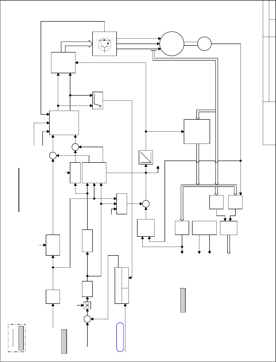
Voltage
Feedforward
Model
Motor Control
Ovr_MCtrl.vsd
Innovation Control
Device name: Date:
01
02
03
04
05
06
07
08
09
10
11
12
13
14
15
16
GE Motors and
Industrial Systems
Salem, Va. USA
PRODUCT:
01
02
03
04
05
06
07
08
09
10
11
12
13
14
15
A B C D E F G H I J K L M N O P Q R S T U
A B C D E F G H I J K L
June 1, 1998
saved date:
Page name:
Σ
+
+
Σ
+
+
Vx
*
Vy
*
Voltage
Regulation
&
Dc bus
Compensation
Σ
+
+
Flux Current
Generation
(Sat-Curve)
Vector
Demodulation
of
Voltage
and
Current
Σ
+
+
Tach
Loss
Detection
Control
On-line
R1
Adaption
On-line
R2
Adaption
Motor
Thermal
Model
Estimated R1 &R2
Motor
Flux
and
Torque
Cal.
Speed
Estima-
tion
Angle
Freq.
Speed
Ix, Iy
Vx, Vy
Voltages & Currents
Command
Flux
Ramping
Slip
Generation
Vector
Rotate
&
PWM
Modulation
Induction
Motor
Flux
Current
Regulation
Slew
Rate
Limit
Torque
Current
Regulation
X + Y
2 2
Overview
Back to Overview
NAVIGATION
Tach
(option)
From Motor
Control Interface
Core
To Speed Feedback
Spd_Fbk
Field-Weakening Control
Modulation
Index Limit
Voltage
Limit
Integrator
Flux ref ratio
Motor flux
Torque fbk, calced
Flux reference
Torque axis volt fbk
Flux axis volt fbk
DC bus feedback
Y axis modulation
X axis modulation
Torque cur fbk unfil
Flux cur fbk unfil
Flux current ref
Modulation index
Jun 06, 2000ISD1
Torque current ref
Torque cur fbk unfil
Slewed trq cur ref
Field weak ctl out
100% Flux
Calculated speed
Output frequency
Crossover Voltage
<No Value> V rms
Voltage
Feedforward
Model
Motor Control
Ovr_MCtrl.vsd
Innovation Control
Device name: Date:
01
02
03
04
05
06
07
08
09
10
11
12
13
14
15
16
GE Motors and
Industrial Systems
Salem, Va. USA
PRODUCT:
01
02
03
04
05
06
07
08
09
10
11
12
13
14
15
A B C D E F G H I J K L M N O P Q R S T U
A B C D E F G H I J K L
June 1, 1998
saved date:
Page name:
Σ
+
+
Σ
+
+
Vx
*
Vy
*
Voltage
Regulation
&
Dc bus
Compensation
Σ
+
+
Flux Current
Generation
(Sat-Curve)
Vector
Demodulation
of
Voltage
and
Current
Σ
+
+
Tach
Loss
Detection
Control
On-line
R1
Adaption
On-line
R2
Adaption
Motor
Thermal
Model
Estimated R1 &R2
Motor
Flux
and
Torque
Cal.
Speed
Estima-
tion
Angle
Freq.
Speed
Ix, Iy
Vx, Vy
Voltages & Currents
Command
Flux
Ramping
Slip
Generation
Vector
Rotate
&
PWM
Modulation
Induction
Motor
Flux
Current
Regulation
Slew
Rate
Limit
Torque
Current
Regulation
X + Y
2 2
Overview
Back to Overview
NAVIGATION
Tach
(option)
From Motor
Control Interface
Core
To Speed Feedback
Spd_Fbk
Field-Weakening Control
Modulation
Index Limit
Voltage
Limit
Integrator
Flux ref ratio
Motor flux
Torque fbk, calced
Flux reference
Torque axis volt fbk
Flux axis volt fbk
DC bus feedback
Y axis modulation
X axis modulation
Torque cur fbk unfil
Flux cur fbk unfil
Flux current ref
Modulation index
Jun 06, 2000ISD1
Torque current ref
Torque cur fbk unfil
Slewed trq cur ref
Field weak ctl out
100% Flux
Calculated speed
Output frequency
Crossover Voltage
<No Value> V rms