
- General Electric Computer Accessories User Manual

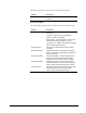
Table Of Contents
- Safety Symbol Legend
- Chapter 1 Overview
- Chapter 2 Faults and Troubleshooting
- Chapter 3 Paramters/Functions
- Introduction
- Diagnostic and Utility Functions
- Drive Configuration Functions
- General Setup Functions
- I/O Functions
- LAN Functions
- Motor Control Functions
- Protective Functions
- Custom User Faults
- DC Link Protection
- Ground Fault Protection (Fast)
- Hardware Fault Strings
- Heatsink Thermal Protection
- Line-Line Voltage Protection
- Motor Overtemperature Detection
- Phase Current Protection
- Timed Overcurrent Detection
- Transformer Overtemperature Detection
- Motor Ground Protection
- Phase Imbalance Monitor
- Line Monitor
- Phase Lock Loop
- Sequencer Functions
- Speed Reference Functions
- Speed/Torque Control Functions
- System Data Parameters
- Chapter 4 Wizards
- Introduction
- Introduction 4-1
- DAC Setup
- Drive Commissioning
- Drive Commissioning: Overview
- Drive Commissioning: Intelligent Part Number
- Drive Commissioning: Drive Units
- Drive Commissioning: AC Source Selection
- Drive Commissioning: Motor Nameplate Data
- Drive Commissioning: Motor Crossover Voltage
- Drive Commissioning: Motor Protection Class
- Drive Commissioning: Motor Poles
- Drive Commissioning: Motor Data Sheet
- Drive Commissioning: Motor Data Sheet - Equivalent Circuit Data
- Drive Commissioning: Motor Data Sheet - Flux Curve
- Drive Commissioning: Motor and Process Speed Referencing
- Drive Commissioning: Tachometer Support
- Drive Commissioning: Tachometer Pulses Per Revolution
- Drive Commissioning: Tachometer Loss Protection
- Drive Commissioning: Stopping Configuration
- Drive Commissioning: Flying Restart
- Drive Commissioning: X-Stop Configuration
- Drive Commissioning: X-Stop Ramp Time
- Drive Commissioning: Run Ready Permissive String
- Drive Commissioning: Starting and Stopping the Drive
- Drive Commissioning: Manual Reference
- Drive Commissioning: Maximum Speed References
- Drive Commissioning: Jog Speed Setpoints
- Drive Commissioning: Reference Ramp Bypass
- Drive Commissioning: Reference Ramp Mode
- Drive Commissioning: Reference Ramp Speed Independent Rates
- Drive Commissioning: Reference Ramp Speed Independent Rate Set Selection
- Drive Commissioning: Reference Ramp Programmed Acceleration Rates
- Drive Commissioning: Reference Ramp Programmed Acceleration Speeds
- Drive Commissioning: Reference Ramp Programmed Deceleration Rates
- Drive Commissioning: Reference Ramp Programmed Deceleration Speeds
- Drive Commissioning: DDI Increment and Decrement Rates (Local Mode)
- Drive Commissioning: Speed/Torque Regulator Configuration
- Drive Commissioning: Speed/Torque Regulator Modes
- Drive Commissioning: Torque Regulator Reference and Output
- Drive Commissioning: Torque with Speed Override Reference and Output
- Drive Commissioning: Torque with Speed Override Speed Error
- Drive Commissioning: Torque with Speed Override Stopping Behavior
- Drive Commissioning: Torque and Current Limits
- Drive Commissioning: Torque and Current Limits Uniform
- Drive Commissioning: Failed Calculation
- Drive Commissioning: Torque and Current Limit Selection
- Drive Commissioning: Normal Torque and Current Limits
- Drive Commissioning: Alternate Torque and Current Limits
- Drive Commissioning: Motoring Torque Limits
- Drive Commissioning: Generating Torque Limits
- Drive Commissioning: Current Limits
- Drive Commissioning: Power Dip Ride-Through
- Drive Commissioning: Parameter Calculation
- Drive Commissioning: Simulator Mode
- Drive Commissioning: Hardware Fault Strings in Simulator Mode
- Drive Commissioning: Simulator Mechanical Configuration
- Drive Commissioning: Exit Reminder
- Drive Commissioning: Conclusion
- Line Transfer Tuneup
- Motor Control Tuneup
- Panel Meter Setup
- Per Unit Setup
- Line Protection Setup
- Pulse Test
- Remaining Parameter Setup
- Simulator Setup
- Speed Regulator Tuneup
- Speed Regulator Tuneup: Model
- Speed Regulator Tuneup: System Inertia
- Speed Regulator Tuneup: Inertia Measurement Command
- Speed Regulator Tuneup: Speed Regulator Mode
- Speed Regulator Tuneup: Manual Regulator Tuneup
- Speed Regulator Tuneup: 1st Order Response
- Speed Regulator Tuneup: 2nd Order Response
- Speed Regulator Tuneup: 2nd Order Response with Stiffness Filter
- Speed Regulator Tuneup: Calculate Speed Regulator Gains Command
- Notes
- Chapter 5 Signal Mapping
- Appendix A Function Block Diagrams
- Index
- Reader Comments

2-36
•
••
•
Chapter 2 Faults and Troubleshooting Innovation Series Medium Voltage GP Type - G Drives GEH-6385
No. Name Type Description
153 DSPx Watchdog
Trip
Locke
d
The DSPx Watchdog trip fault occurs when the DSPX EPLD stops seeing a
watchdog toggle bit from the processor. A hard reset occurs and the fault is
declared at initialization.
DSPx Watchdog requires a hard reset to clear.
Possible board failures:
DSPX
154 Reverse rotation Trip The Reverse rotation trip fault occurs when the motor shaft is rotating opposite
to the requested direction.
Related functions:
Speed Control Fault Check
155 Failure to rotate Trip
The Failure to rotate trip fault occurs when speed regulator error grows large
while the speed feedback is small.
Related functions:
Speed Control Fault Check
156 Loss of spd control Alarm
The Loss of spd control trip fault occurs when the speed regulator error is too
large.
Related functions:
Speed Control Fault Check
157 Bic Watchdog Trip The Bic Watchdog trip fault occurs when the BICM stops seeing a watchdog
toggle bit from the DSPX. When the drive is running, BICM monitors a toggle
bit being manipulated by DSPX. If DSPX does not toggle the bit on BICM
within a predefined time interval, the BICM declares a fault and disables the
bridge. This indicates that the processor cannot communicate reliably with the
bridge interface card.
Bic Watchdog requires a hard reset to clear.
Possible configuration faults:
The connected drive is a simulator but Simulate mode act is equal to False.
Set Simulate mode equal to Yes to correct the problem.
Possible board failures:
BICM
DSPX
CABP (backplane)
158 Bic watchdog echo Trip
The Bic watchdog echo trip fault occurs when the DSPX stops seeing the echo
of the watchdog toggle bit that it writes to the BICM. This indicates that the
processor cannot communicate reliably with the bridge interface card.
Primary Causes:
Bent backplane connector pins or poorly seated cards.
Possible board failures:
BICM
DSPX
CABP (backplane)
160 LAN trip request Trip The LAN trip request trip fault occurs when a request for a trip fault is received
from the LAN by assertion of the reference Boolean signal Trip request, lan.
161 LAN alarm request Alarm The LAN alarm request alarm occurs when a request for an alarm is received
from the LAN by assertion of the reference Boolean signal Alarm request, lan.