
- General Electric Computer Accessories User Manual

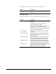
Table Of Contents
- Safety Symbol Legend
- Chapter 1 Overview
- Chapter 2 Faults and Troubleshooting
- Chapter 3 Paramters/Functions
- Introduction
- Diagnostic and Utility Functions
- Drive Configuration Functions
- General Setup Functions
- I/O Functions
- LAN Functions
- Motor Control Functions
- Protective Functions
- Custom User Faults
- DC Link Protection
- Ground Fault Protection (Fast)
- Hardware Fault Strings
- Heatsink Thermal Protection
- Line-Line Voltage Protection
- Motor Overtemperature Detection
- Phase Current Protection
- Timed Overcurrent Detection
- Transformer Overtemperature Detection
- Motor Ground Protection
- Phase Imbalance Monitor
- Line Monitor
- Phase Lock Loop
- Sequencer Functions
- Speed Reference Functions
- Speed/Torque Control Functions
- System Data Parameters
- Chapter 4 Wizards
- Introduction
- Introduction 4-1
- DAC Setup
- Drive Commissioning
- Drive Commissioning: Overview
- Drive Commissioning: Intelligent Part Number
- Drive Commissioning: Drive Units
- Drive Commissioning: AC Source Selection
- Drive Commissioning: Motor Nameplate Data
- Drive Commissioning: Motor Crossover Voltage
- Drive Commissioning: Motor Protection Class
- Drive Commissioning: Motor Poles
- Drive Commissioning: Motor Data Sheet
- Drive Commissioning: Motor Data Sheet - Equivalent Circuit Data
- Drive Commissioning: Motor Data Sheet - Flux Curve
- Drive Commissioning: Motor and Process Speed Referencing
- Drive Commissioning: Tachometer Support
- Drive Commissioning: Tachometer Pulses Per Revolution
- Drive Commissioning: Tachometer Loss Protection
- Drive Commissioning: Stopping Configuration
- Drive Commissioning: Flying Restart
- Drive Commissioning: X-Stop Configuration
- Drive Commissioning: X-Stop Ramp Time
- Drive Commissioning: Run Ready Permissive String
- Drive Commissioning: Starting and Stopping the Drive
- Drive Commissioning: Manual Reference
- Drive Commissioning: Maximum Speed References
- Drive Commissioning: Jog Speed Setpoints
- Drive Commissioning: Reference Ramp Bypass
- Drive Commissioning: Reference Ramp Mode
- Drive Commissioning: Reference Ramp Speed Independent Rates
- Drive Commissioning: Reference Ramp Speed Independent Rate Set Selection
- Drive Commissioning: Reference Ramp Programmed Acceleration Rates
- Drive Commissioning: Reference Ramp Programmed Acceleration Speeds
- Drive Commissioning: Reference Ramp Programmed Deceleration Rates
- Drive Commissioning: Reference Ramp Programmed Deceleration Speeds
- Drive Commissioning: DDI Increment and Decrement Rates (Local Mode)
- Drive Commissioning: Speed/Torque Regulator Configuration
- Drive Commissioning: Speed/Torque Regulator Modes
- Drive Commissioning: Torque Regulator Reference and Output
- Drive Commissioning: Torque with Speed Override Reference and Output
- Drive Commissioning: Torque with Speed Override Speed Error
- Drive Commissioning: Torque with Speed Override Stopping Behavior
- Drive Commissioning: Torque and Current Limits
- Drive Commissioning: Torque and Current Limits Uniform
- Drive Commissioning: Failed Calculation
- Drive Commissioning: Torque and Current Limit Selection
- Drive Commissioning: Normal Torque and Current Limits
- Drive Commissioning: Alternate Torque and Current Limits
- Drive Commissioning: Motoring Torque Limits
- Drive Commissioning: Generating Torque Limits
- Drive Commissioning: Current Limits
- Drive Commissioning: Power Dip Ride-Through
- Drive Commissioning: Parameter Calculation
- Drive Commissioning: Simulator Mode
- Drive Commissioning: Hardware Fault Strings in Simulator Mode
- Drive Commissioning: Simulator Mechanical Configuration
- Drive Commissioning: Exit Reminder
- Drive Commissioning: Conclusion
- Line Transfer Tuneup
- Motor Control Tuneup
- Panel Meter Setup
- Per Unit Setup
- Line Protection Setup
- Pulse Test
- Remaining Parameter Setup
- Simulator Setup
- Speed Regulator Tuneup
- Speed Regulator Tuneup: Model
- Speed Regulator Tuneup: System Inertia
- Speed Regulator Tuneup: Inertia Measurement Command
- Speed Regulator Tuneup: Speed Regulator Mode
- Speed Regulator Tuneup: Manual Regulator Tuneup
- Speed Regulator Tuneup: 1st Order Response
- Speed Regulator Tuneup: 2nd Order Response
- Speed Regulator Tuneup: 2nd Order Response with Stiffness Filter
- Speed Regulator Tuneup: Calculate Speed Regulator Gains Command
- Notes
- Chapter 5 Signal Mapping
- Appendix A Function Block Diagrams
- Index
- Reader Comments

GEH-6385 Reference and Troubleshooting, 2300 V Drives Chapter 2 Faults and Troubleshooting
•
••
•
2-37
No. Name Type Description
162
LAN watchdog
alarm
Alarm
The LAN watchdog alarm occurs when the connection between DSPX and the
Application/LAN interface becomes invalid. This includes one of the following
conditions, depending upon the selection of Network interface:
The Application/LAN interface Dual-Port RAM watchdog stops.
The ISBus frames stop.
The alarm is declared after the condition persists for several hundred
microseconds.
163
Restrictd fcn
enabld
Alarm
The Restrictd fcn enabld alarm occurs when the selected execution time base
in the parameter Exec time/Chop freq restricts certain drive functionality due to
timing limitations, or the ISBus network is selected by the Network interface
parameter and the DSPX hardware does not support ISBus. Certain functions
that are presently enabled will not run.
Possible configuration faults:
Execution time base is too low. Select alternate time base in parameter Exec
time/Chop freq.
LAN is enabled, but will not operate. Disable LAN by setting parameter
Network interface to None.
ISBus is selected, but will not operate. Deselect ISBus by setting parameter
Network interface, or replace the DSPX HIA with a DSPX H1B.
164 LAN heartbeat trip Trip The LAN heartbeat trip occurs when all of the following conditions are present:
Non-zero value is entered in Parameter LAN heartbeat time.
The signal (Heartbeat ref, lan) fails to transition within in that time.
The trip behavior is enabled by Parameter LAN trips inhibit.
The LAN connection ok condition was previously detected.
165
LAN heartbeat
alarm
Alarm
The LAN heartbeat alarm occurs when all of the following conditions are
present:
Non-zero value is entered in Parameter LAN heartbeat time.
The signal (Heartbeat ref, lan) fails to transition within in that time.
Either the trip behavior is inhibited by Parameter LAN trips inhibit, or the trip
behavior is enabled but the LAN connection ok condition was not previously
detected.
166
Requird Parm
Missing
Trip
The Requird Parm Missing trip fault occurs when one of the required
parameters either is not entered, “No Value” or has a value of zero. Check the
following values, which can be found in the commissioning wizard.
Primary causes:
Motor rated voltage, Not entered
Motor rated freq, Not entered
Motor rated current, Not entered
Motor rated rpm, Not entered
Motor rated power, Not entered
Motor service factor, Not entered
167 Version mismatch Trip The Version mismatch trip fault occurs at initialization when the drive pattern
detects a product or version mismatch with the parameters stored in non-
volatile RAM. Download parameters to fix.
168 System ISBus error Alarm The System ISBus error alarm occurs when an ISBus fault is detected in the
DSPX control. The variable Sys ISBus error reg contains the bit-coded value
of the last ISBus fault detected; each bit indicates a particular ISBus fault seen
by the control. The variable Sys ISBus error cnt increments upon fault
detection.
Record the value of Sys ISBus error reg to assist factory troubleshooting
efforts. Monitor the progression of Sys ISBus error cnt to obtain an indication
of the rate of occurrence of fault conditions.
Transient occurrence of this alarm upon initialization of the interface is
expected.