
- General Electric Computer Accessories User Manual

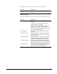
Table Of Contents
- Safety Symbol Legend
- Chapter 1 Overview
- Chapter 2 Faults and Troubleshooting
- Chapter 3 Paramters/Functions
- Introduction
- Diagnostic and Utility Functions
- Drive Configuration Functions
- General Setup Functions
- I/O Functions
- LAN Functions
- Motor Control Functions
- Protective Functions
- Custom User Faults
- DC Link Protection
- Ground Fault Protection (Fast)
- Hardware Fault Strings
- Heatsink Thermal Protection
- Line-Line Voltage Protection
- Motor Overtemperature Detection
- Phase Current Protection
- Timed Overcurrent Detection
- Transformer Overtemperature Detection
- Motor Ground Protection
- Phase Imbalance Monitor
- Line Monitor
- Phase Lock Loop
- Sequencer Functions
- Speed Reference Functions
- Speed/Torque Control Functions
- System Data Parameters
- Chapter 4 Wizards
- Introduction
- Introduction 4-1
- DAC Setup
- Drive Commissioning
- Drive Commissioning: Overview
- Drive Commissioning: Intelligent Part Number
- Drive Commissioning: Drive Units
- Drive Commissioning: AC Source Selection
- Drive Commissioning: Motor Nameplate Data
- Drive Commissioning: Motor Crossover Voltage
- Drive Commissioning: Motor Protection Class
- Drive Commissioning: Motor Poles
- Drive Commissioning: Motor Data Sheet
- Drive Commissioning: Motor Data Sheet - Equivalent Circuit Data
- Drive Commissioning: Motor Data Sheet - Flux Curve
- Drive Commissioning: Motor and Process Speed Referencing
- Drive Commissioning: Tachometer Support
- Drive Commissioning: Tachometer Pulses Per Revolution
- Drive Commissioning: Tachometer Loss Protection
- Drive Commissioning: Stopping Configuration
- Drive Commissioning: Flying Restart
- Drive Commissioning: X-Stop Configuration
- Drive Commissioning: X-Stop Ramp Time
- Drive Commissioning: Run Ready Permissive String
- Drive Commissioning: Starting and Stopping the Drive
- Drive Commissioning: Manual Reference
- Drive Commissioning: Maximum Speed References
- Drive Commissioning: Jog Speed Setpoints
- Drive Commissioning: Reference Ramp Bypass
- Drive Commissioning: Reference Ramp Mode
- Drive Commissioning: Reference Ramp Speed Independent Rates
- Drive Commissioning: Reference Ramp Speed Independent Rate Set Selection
- Drive Commissioning: Reference Ramp Programmed Acceleration Rates
- Drive Commissioning: Reference Ramp Programmed Acceleration Speeds
- Drive Commissioning: Reference Ramp Programmed Deceleration Rates
- Drive Commissioning: Reference Ramp Programmed Deceleration Speeds
- Drive Commissioning: DDI Increment and Decrement Rates (Local Mode)
- Drive Commissioning: Speed/Torque Regulator Configuration
- Drive Commissioning: Speed/Torque Regulator Modes
- Drive Commissioning: Torque Regulator Reference and Output
- Drive Commissioning: Torque with Speed Override Reference and Output
- Drive Commissioning: Torque with Speed Override Speed Error
- Drive Commissioning: Torque with Speed Override Stopping Behavior
- Drive Commissioning: Torque and Current Limits
- Drive Commissioning: Torque and Current Limits Uniform
- Drive Commissioning: Failed Calculation
- Drive Commissioning: Torque and Current Limit Selection
- Drive Commissioning: Normal Torque and Current Limits
- Drive Commissioning: Alternate Torque and Current Limits
- Drive Commissioning: Motoring Torque Limits
- Drive Commissioning: Generating Torque Limits
- Drive Commissioning: Current Limits
- Drive Commissioning: Power Dip Ride-Through
- Drive Commissioning: Parameter Calculation
- Drive Commissioning: Simulator Mode
- Drive Commissioning: Hardware Fault Strings in Simulator Mode
- Drive Commissioning: Simulator Mechanical Configuration
- Drive Commissioning: Exit Reminder
- Drive Commissioning: Conclusion
- Line Transfer Tuneup
- Motor Control Tuneup
- Panel Meter Setup
- Per Unit Setup
- Line Protection Setup
- Pulse Test
- Remaining Parameter Setup
- Simulator Setup
- Speed Regulator Tuneup
- Speed Regulator Tuneup: Model
- Speed Regulator Tuneup: System Inertia
- Speed Regulator Tuneup: Inertia Measurement Command
- Speed Regulator Tuneup: Speed Regulator Mode
- Speed Regulator Tuneup: Manual Regulator Tuneup
- Speed Regulator Tuneup: 1st Order Response
- Speed Regulator Tuneup: 2nd Order Response
- Speed Regulator Tuneup: 2nd Order Response with Stiffness Filter
- Speed Regulator Tuneup: Calculate Speed Regulator Gains Command
- Notes
- Chapter 5 Signal Mapping
- Appendix A Function Block Diagrams
- Index
- Reader Comments

3-6
•
••
•
Chapter 3 Paramters/Functions Innovation Series Medium Voltage GP Type - G Drives GEH-6385
Function Configuration
The following table specifies the parameters that configure the size and execution
rate of the capture buffer.
Parameter Description
Capture buff config
Specifies the number of channels to collect. The depth
of the capture buffer is inversely proportional to the
number of channels collected. Possible values are:
2 channels enabled
4 channels enabled
8 channels enabled
Note Whenever this parameter is modified, the
capture buffer must be re-enabled to collect data with
the new channel configuration.
Capture period
Determines the rate at which the capture buffer collects
data. Each rate in the enumeration list is based on a
particular execution rate in the processor. Actual
execution rates vary between each Innovation Series
product. Possible values are:
Disable - Disables the capture buffer from collecting
data.
Task 1 rate - Collects data at the fastest execution rate
of the processor.
Task 2 rate - Collects data at n times slower than Task
1 rate. (n Task 1’s are executed every 1 Task 2).
Task 3 rate - Collects data at m times slower than Task
2 rate. (m Task 2’s are executed every 1 Task 3).
Note Whenever this parameter is modified, the
capture buffer must be re-enabled to collect data at the
new rate.
Capture period gain Increases the collection period of the capture buffer
(data is collected at a slower rate). For an integer
value, n (>1), the capture buffer would collect data
every n
th
execution of the Capture period.
Cap re-enable delay
Controls an auto re-enable function for the capture
buffer. This parameter sets the delay from when the
capture buffer has completed its collection to when the
capture buffer is re-enabled automatically. Minutes.
The capture buffer will only re-enable when the drive is
not stopped (Stopped is False). If Cap re-enable delay
expires when the drive is stopped, the capture buffer
will not re-enable until the drive is running again.
Note A value of –1 disables the auto re-enable
function.