
- General Electric Computer Accessories User Manual
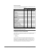

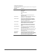
Table Of Contents
- Safety Symbol Legend
- Chapter 1 Overview
- Chapter 2 Faults and Troubleshooting
- Chapter 3 Paramters/Functions
- Introduction
- Diagnostic and Utility Functions
- Drive Configuration Functions
- General Setup Functions
- I/O Functions
- LAN Functions
- Motor Control Functions
- Protective Functions
- Custom User Faults
- DC Link Protection
- Ground Fault Protection (Fast)
- Hardware Fault Strings
- Heatsink Thermal Protection
- Line-Line Voltage Protection
- Motor Overtemperature Detection
- Phase Current Protection
- Timed Overcurrent Detection
- Transformer Overtemperature Detection
- Motor Ground Protection
- Phase Imbalance Monitor
- Line Monitor
- Phase Lock Loop
- Sequencer Functions
- Speed Reference Functions
- Speed/Torque Control Functions
- System Data Parameters
- Chapter 4 Wizards
- Introduction
- Introduction 4-1
- DAC Setup
- Drive Commissioning
- Drive Commissioning: Overview
- Drive Commissioning: Intelligent Part Number
- Drive Commissioning: Drive Units
- Drive Commissioning: AC Source Selection
- Drive Commissioning: Motor Nameplate Data
- Drive Commissioning: Motor Crossover Voltage
- Drive Commissioning: Motor Protection Class
- Drive Commissioning: Motor Poles
- Drive Commissioning: Motor Data Sheet
- Drive Commissioning: Motor Data Sheet - Equivalent Circuit Data
- Drive Commissioning: Motor Data Sheet - Flux Curve
- Drive Commissioning: Motor and Process Speed Referencing
- Drive Commissioning: Tachometer Support
- Drive Commissioning: Tachometer Pulses Per Revolution
- Drive Commissioning: Tachometer Loss Protection
- Drive Commissioning: Stopping Configuration
- Drive Commissioning: Flying Restart
- Drive Commissioning: X-Stop Configuration
- Drive Commissioning: X-Stop Ramp Time
- Drive Commissioning: Run Ready Permissive String
- Drive Commissioning: Starting and Stopping the Drive
- Drive Commissioning: Manual Reference
- Drive Commissioning: Maximum Speed References
- Drive Commissioning: Jog Speed Setpoints
- Drive Commissioning: Reference Ramp Bypass
- Drive Commissioning: Reference Ramp Mode
- Drive Commissioning: Reference Ramp Speed Independent Rates
- Drive Commissioning: Reference Ramp Speed Independent Rate Set Selection
- Drive Commissioning: Reference Ramp Programmed Acceleration Rates
- Drive Commissioning: Reference Ramp Programmed Acceleration Speeds
- Drive Commissioning: Reference Ramp Programmed Deceleration Rates
- Drive Commissioning: Reference Ramp Programmed Deceleration Speeds
- Drive Commissioning: DDI Increment and Decrement Rates (Local Mode)
- Drive Commissioning: Speed/Torque Regulator Configuration
- Drive Commissioning: Speed/Torque Regulator Modes
- Drive Commissioning: Torque Regulator Reference and Output
- Drive Commissioning: Torque with Speed Override Reference and Output
- Drive Commissioning: Torque with Speed Override Speed Error
- Drive Commissioning: Torque with Speed Override Stopping Behavior
- Drive Commissioning: Torque and Current Limits
- Drive Commissioning: Torque and Current Limits Uniform
- Drive Commissioning: Failed Calculation
- Drive Commissioning: Torque and Current Limit Selection
- Drive Commissioning: Normal Torque and Current Limits
- Drive Commissioning: Alternate Torque and Current Limits
- Drive Commissioning: Motoring Torque Limits
- Drive Commissioning: Generating Torque Limits
- Drive Commissioning: Current Limits
- Drive Commissioning: Power Dip Ride-Through
- Drive Commissioning: Parameter Calculation
- Drive Commissioning: Simulator Mode
- Drive Commissioning: Hardware Fault Strings in Simulator Mode
- Drive Commissioning: Simulator Mechanical Configuration
- Drive Commissioning: Exit Reminder
- Drive Commissioning: Conclusion
- Line Transfer Tuneup
- Motor Control Tuneup
- Panel Meter Setup
- Per Unit Setup
- Line Protection Setup
- Pulse Test
- Remaining Parameter Setup
- Simulator Setup
- Speed Regulator Tuneup
- Speed Regulator Tuneup: Model
- Speed Regulator Tuneup: System Inertia
- Speed Regulator Tuneup: Inertia Measurement Command
- Speed Regulator Tuneup: Speed Regulator Mode
- Speed Regulator Tuneup: Manual Regulator Tuneup
- Speed Regulator Tuneup: 1st Order Response
- Speed Regulator Tuneup: 2nd Order Response
- Speed Regulator Tuneup: 2nd Order Response with Stiffness Filter
- Speed Regulator Tuneup: Calculate Speed Regulator Gains Command
- Notes
- Chapter 5 Signal Mapping
- Appendix A Function Block Diagrams
- Index
- Reader Comments

GEH-6385 Reference and Troubleshooting, 2300 V Drives Chapter 3 Paramters/Functions
•
••
•
3-33
Digital Inputs/Outputs and Mapping
Digital inputs and outputs provide an interface between the outside world and the
control. The ATB (terminal board) provides six general purpose digital inputs.
Three dry contact relays and one solid state relay driver are provided as outputs.
System and Local fault strings provide start and trip interlocks to the control.
Isolated digital inputs are listed with their associated terminal board points. A filter
debounces a noisy input signal. The filter should be set to zero in most instances,
since the hardware provides a level of debounce conditioning. The variables Digital
input 1 through Digital input 6 indicate the logical state of each digital input and are
used to interface to functions in the drive that require a Boolean signal.
Each relay output may be used by setting the parameters Relay 1 select through
Relay 3 select to the variables whose logical states are desired to drive the
corresponding relay. The associated terminal board points are shown for output
terminals of each relay. The variables Relay 1 state, Relay 2 state, and Relay 3 state
indicates whether the relay coils are energized.
Relay four is a solid-state relay driver that should be used for driving a 24 V dc, 10
mA relay. The relay driver output may be used by setting the parameter SS relay
driver sel to the variable whose logical state is desired to drive the relay. Solid state
relay indicates the status of the relay driver.
In addition to the four programmable outputs available on ATB, the drive provides 3
additional application outputs through the CTBC terminal board. The CTBC outputs
are not programmable but instead are mapped to some commonly used signals in the
drive. CTBC outputs are solid-state relay drivers that can be used for driving 24 V
dc, 10 mA relays. Signals available on CTBC are as follows:
CTBC Output Pre-programmed function
D08 (pins 33 & 35)
D07 (pins 29 & 31)
D06 (pins 25 & 27)
Closed when No trip fault is True
Closed when Running is True
Closed when No faults active is True
A pilot relay controls a main contactor. Most applications do not require a contactor
(see MA contactor absent). This contactor is normally controlled through drive
sequencing, but it may be controlled alternately by MA close req sel. The contactor
cannot be energized if either the Local Fault String or the System Fault String are
open. If the contactor is closed and the Local Fault String or the System Fault String
open, the contactor will be de-energized.
Contactor status feedback is available (MA contactor closed). MA contactor fbk
determines if the drive sequencer requires MA contactor closed to be active in
response to a contactor close command.
Related diagrams
• Digital Inputs / Outputs & Mapping (HWIO_Dig)